基本信息
对齐用于根据单一、唯一的参考对象调整执行 ROI(或其他相关 ROI,如模型 ROI,取决于视觉功能)的位置(X、Y)和方向。后续视觉功能的 ROI 是在配置阶段相对于该参考对象定义的。这个相对位置保持不变,以配置中参考对象的位置和方向为基准。
对齐数据可由以下视觉功能提供:
•读码器
•图像块
•匹配
就导出对齐数据的预期精度而言,最适合的是基于二维码的匹配和读码器,其次是子像素 Blob和Blob。
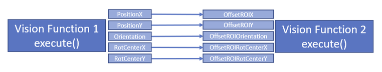
如果将视觉功能设置为对齐参考,对齐数据将通过过程变量 PositionX、PositionY 和 Orientation 输出。此外,还需要使用 RotCenterX 和 RotCenterY,它们定义了对齐过程中变换的旋转中心。
以下是用于配置的过程变量链接:
旋转对称(完全对称和部分对称)的参照对象仅有条件地适用于提供对齐数据。不过,通常可以对视觉功能进行相应配置,以使用此类参照物。为此,必须在对齐过程中为方向角配置相应的限制(例如,完全对称 → 方向角始终等于 0,部分对称 → 角度范围根据对称性限制在一个子范围内)。如果配置不正确,可能会产生歧义,从而导致对齐值出现意外。
基本程序
应用对齐功能的基本步骤如下:
配置视觉功能 1 (VF 1) 以提供对齐数据:
•将循环参数 Alignment 更改为 1(按执行)。
•配置并在必要时示教一个模型,以找到所需的参照物。
•在同一图像上执行一次 VF 1,为 Alignment 生成参考数据(按执行)。
•只有此时才会保存参考数据,并永久存储(按执行)。
配置视觉功能 2 (VF 2) 以使用对齐功能:
•VF 2 的循环参数 Alignment 保持为 0。
•配置并在必要时调入一个模型。
所有后续图像的顺序:
•执行 VF 1。
•通过输出参数 PositionX/Y、Orientation 和 RotCenterX/Y,提供变换参数(OffsetROIX/Y、OffsetROIOrientation、OffsetROIRotCenterX/Y)。
在 VF 中使用对齐 2:
•通过偏移传送 5 个变换参数。在 VF 2 中对 "执行 ROI"(如有必要)和其他必要参数进行内部自动调整。
•照常输出常规参数。

信息:
参数值只有通过 Execute 传递后才会在目标系统中列出。
信息:
在一次成功的示教过程结束后,始终可以再次示教视觉功能。
但是,如果重新教入对齐源和/或重新设置参照对象,则必须重新教入在该源上镜像的所有视觉功能,因为参照对象可能已经发生了根本性的变化,因此无法再正确地镜像对齐链。
如果一个校准源镜像了多个视觉功能,建议在采集图像时对整个校准链进行示教!
其他信息
可以重新调整校准源(VF 1)中的参数/模型。首先必须将校准设置为 1。调整后,必须再次生成参考数据(执行),然后再将对齐源切换为 2,以便为 VF 2 生成对齐数据。
一般来说,以下操作会自动放弃对齐参考数据:
•将对齐方式更改为 1 或 0。
•对齐方式 = 1 时设置参数。
•对齐 = 1 或 2 时删除模型。
•对齐方式 = 2 时添加或更改/替换模型。
在下列情况下,如果 VF 中的对齐方式没有参考数据,则会输出错误信息:
•将对齐方式从 1 更改为 2。
•将对齐方式从 0 更改为 2。
无法执行以下操作:
•对齐方式 = 2 时添加或修改/替换模型。
•如果没有对齐参考数据,则在对齐 = 2 时执行。
参数会影响基准的查找和位置。因此,可能会丢失对原始参照物的参照,导致 Alignment 返回错误值并失败。因此,在生成基准数据后,不应更改这些参数。示例:
•符号类型(SymbolType)与读码器。
•带有Blob 的 RegionFeatures。
•带匹配的 MinScore、MaxOverlap、Greediness 或 BorderShapeModels。
其他信息
在使用对齐的视觉函数作为参考时,可能会对个别值存在某些限制。
•一般限制
•当执行视觉函数生成 Alignment = 1 的参考数据时,NumSearchMax 会自动设置为 1,并且 PositionX/Y 和 Orientation 的返回值都会设置为 0。
•当执行视觉函数生成 Alignment = 2 的对齐数据时,NumSearchMax 会自动设置为 1。
•当将具有活动对齐功能(偏移值不等于 0)的视觉功能连锁在一起时,测量和像素计数器的 "模型 ROI "会在示教过程中转换为 "无对齐 "状态。
背景:在禁用对齐(偏移值 = 0)的情况下,视觉功能的执行速度应尽可能快。因此,在这种情况下,"Model ROI"(模型 ROI)不应通过 "Execute(执行)"进行转换,而必须在示教过程中事先进行转换。
•匹配
•参数 ModelScaleMin、ModelScaleMax、SearchScaleMin 和 SearchScaleMax 被固定为 1。
•方向值(来自 Execute)总是指每幅图像中的 0° 方向(正列方向);因此,0° 参考方向与图像内容的旋转无关。
•每个模型的 0° 方向都是在教入模型的图像中定义的。因此,如果模型是在不同的对齐状态下教入的,那么这些模型参考方向可能与多个对象不同。因此,这些不同模型的方向值与搜索所有模型的图像执行值不同。
•在将对齐功能应用于视觉功能时,必须考虑已定义模型的某些要求。例如,在视觉功能 "匹配"中,模型的角度范围必须设置为 0° - 360°;否则,"对齐 "将在可能的旋转角度方面受到限制,有时甚至无法找到结果。如果打算使用这种限制,则必须对两个视觉功能(VF 1 和 VF 2)进行相应配置。注意 NCC 模型的数据量尤为重要。根据模板的大小,这里可能会出现非常大的数据量。因此,教入过程也可能需要很长时间。
在教入对象时,搜索角度范围的 0° 方向被定义。该 0° 方向适用于对齐基准,如果对齐发生变化,则会在搜索过程中自动进行内部调整。因此,在执行过程中,方向的结果值(参考值:全局常量,水平列方向)有可能超出该值范围。此外,如果模型是在活动对齐状态下教入的,而随后又要在不同的对齐状态下调整搜索角 度范围,有时也会造成困难。
•读码器 (一维代码)
•在训练中,"方向 "和 "公差 "总是指固定的图像坐标系。因此,如果在优化过程中激活了对齐功能,这些值很可能会大大增加。
因此,在这种情况下,需要在优化后手动调整数值。
信息:
如果不执行优化,而是执行正常的 Execute(执行),则在 Alignment(对齐)情况下会自动在内部调整方向参数。
•在作为对齐源使用时,必须确保搜索对象在外观、尺寸和灰度值上与参考模型保持一致。否则,方向可能会发生变化,导致镜像视觉功能的 ROI 被镜像到不正确的位置,从而产生不正确的结果或根本没有结果。
Alignment is used to adjust the Execute ROI (or other relevant ROIs such as the Model ROI depending on the vision function) in its position (X, Y) and orientation based on a single, unique reference object. The ROI for the subsequent vision function is defined in the configuration phase, relative to this reference object. This relative position remains constant, with the position and orientation of the reference object from the configuration set as the reference.
Alignment data can be provided by the following vision functions:
•Blob
Best suited for this, in terms of the expected accuracy of the derived alignment data, are Matching and Code reader based on a 2D code, followed by Subpixel Blob and Blob.
If a vision function is set as an Alignment reference, data for Alignment is output via process variables PositionX, PositionY and Orientation. In addition, RotCenterX and RotCenterY are required, which define the rotation center for the transformation during Alignment.
The following links of the process variables are given for configuration:
Rotationally symmetric (fully symmetric as well as partially symmetric) reference objects are only conditionally suitable for providing alignment data. The vision function can normally be configured accordingly to use such reference objects, however. For this purpose, corresponding limitations must be configured for orientation angles during Alignment (e.g. fully symmetrical → orientation always equal to 0, partially symmetrical → angle range limited to a subrange according to the symmetry). Ambiguities can occur here if the configuration is incorrect, which can then result in unexpected values for Alignment.
Basic procedure
The basic procedure for applying Alignment is as follows:
Configuring vision function 1 (VF 1) to provide Alignment data:
•Change cyclic parameter Alignment to 1 (press Execute).
•Configure and, if necessary, teach-in a model to find the desired reference object.
•Execute VF 1 once on the same image to generate the reference data for Alignment (press Execute).
•Change Alignment to 2. Only now is the reference data saved and thus permanently stored (press Execute).
Configuring vision function 2 (VF 2) to use an alignment:
•Cyclic parameter Alignment of VF 2 remains at 0.
•Configure and, if necessary, teach-in a model.
Sequence for all following images:
•Execute VF 1.
•Provide the transformation parameters (OffsetROIX/Y, OffsetROIOrientation, OffsetROIRotCenterX/Y) via output parameters PositionX/Y, Orientation and RotCenterX/Y.
Using an alignment in VF 2:
•Transfer the 5 transformation parameters via offset. Internal automatic adjustment of the "Execute ROI" (if necessary) and other necessary parameters in VF 2.
•Output the usual parameters as usual.
Information:
The values of a parameter are only listed on the target system as soon as they are passed by Execute.
Information:
It is always possible to teach-in a vision function again after the completion of a successful teach-in process.
However, if the alignment source is taught-in again and/or the reference object is re-set, all the vision functions mirrored at this source must be taught-in again since the reference may have changed fundamentally and the alignment chain can no longer be mirrored correctly as a result.
If several vision functions are mirrored by an alignment source, it is recommended that the entire alignment chain is taught-in with an image acquisition!
Additional information
Readjustment of parameters/models in the alignment source (VF 1) is possible. Alignment must first be set to 1. After the adjustments, generating the reference data is necessary again (Execute) before Alignment is switched to 2 again in order to generate alignment data for VF 2.
In general, the alignment reference data is automatically discarded for the following actions:
•Changing Alignment to 1 or 0.
•Setting parameters when Alignment = 1.
•Removing models when Alignment = 1 or 2.
•Adding or changing/replacing a model when Alignment = 2.
In the following cases, an error is output if reference data is not available for Alignment in the VF:
•Changing Alignment from 1 to 2.
•Changing Alignment from 0 to 2.
The following actions are not possible:
•Adding or modifying/replacing models when Alignment = 2.
•Executed when Alignment = 2 if no alignment reference data is available.
Parameters can influence the finding and position of the reference. As a result, the reference to the original reference may be lost, causing Alignment to return incorrect values and fail. These parameters should therefore not be changed after the reference data has been generated. Examples:
•SymbolType with Code reader.
•RegionFeatures with Blob.
•MinScore, MaxOverlap, Greediness or BorderShapeModels with Matching.
Additional information
When using a vision function for Alignment as a reference, certain restrictions may exist for individual values.
•General
•NumSearchMax is automatically set to 1 and the return values for PositionX/Y and Orientation are all set to 0 when executing a vision function to generate reference data with Alignment = 1.
•NumSearchMax is automatically set to 1 when executing a vision function to generate alignment data with Alignment = 2.
•When chaining together vision functions with active Alignment (offset values not equal to 0), the "Model ROI" for Measurement and Pixel counter is transformed to state "No alignment" during the teach-in process.
Background: The execution of the vision function should be as fast as possible with disabled Alignment (offset values = 0). A transformation of the "Model ROI" should therefore not take place with "Execute" in this case and must be carried out beforehand during the teach-in process.
•Parameters ModelScaleMin, ModelScaleMax, SearchScaleMin and SearchScaleMax are fixed to 1.
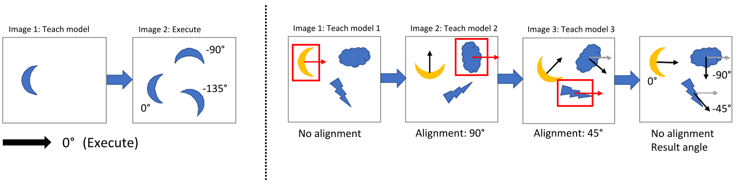
•The orientation values (from Execute) always refer to the 0° direction (positive column direction) in each image; this reference direction 0° is therefore independent of a rotation of the image content.
•The 0° orientation for a model is defined in each case in the image in which the model was taught-in. Accordingly, these model reference directions may differ from several objects if they were taught-in in different alignment states. As a consequence, the orientation values of these different models differ from an Execute of an image where all models are searched.
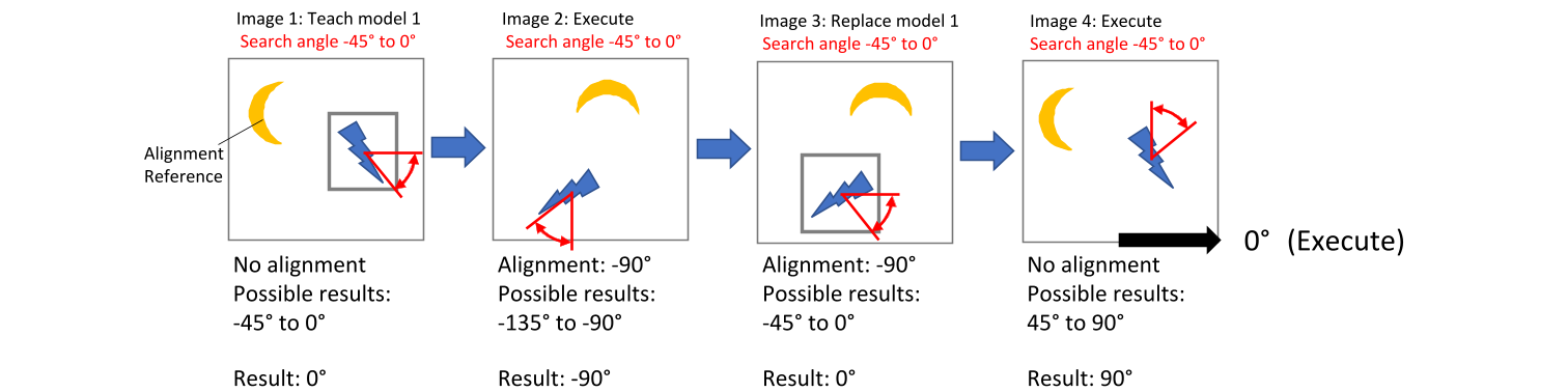
•When applying Alignment to a vision function, certain requirements must be taken into account for the defined models. With vision function Matching, for example, the angle range of the models must be set to 0° - 360°; otherwise, Alignment would be limited with regard to the possible rotation angles, sometimes preventing results from being found. If such a restriction is nevertheless intended, both vision functions (VF 1 and VF 2) must be configured accordingly. It is especially important to note the amount of data for NCC models. Very large amounts of data can occur here, depending on the template size. Accordingly, the teach-in process can also take a long time.
Direction 0° of the search angle range is defined when teaching-in the object. This 0° direction applies with respect to the alignment reference and is automatically adjusted internally during a search if the alignment changes. It is therefore possible that the result values of the orientation (reference: global constant, horizontal column direction) lie outside this range of values during Execute. In addition, it can sometimes cause difficulties if a model is taught-in in an active alignment state and the search angle range should subsequently be adjusted in a different alignment state.
•Code reader (1D codes)
•In a training, Orientation and Tolerance always refer to the fixed image coordinate system. So if Alignment is active during an optimization, it is very likely that the values will be greatly expanded.
Manual adjustment of the values is therefore necessary after optimization in such a case.
Information:
If o optimization is not performed, but a normal Execute is executed, the orientation parameter is automatically adjusted internally in the event of Alignment.
•When used as an alignment source, it is important to ensure that the searched object permanently corresponds to the reference model in appearance, size and grayscale values. Otherwise, Orientation may change so that the ROI of the mirrored vision function is mirrored to an incorrect position, resulting in an incorrect result or no result at all.