IP 地址、子网掩码和节点编号的最佳做法
信息:
推荐的 mapp Vision 最佳实践是为每个要操作摄像机模块的 POWERLINK 接口分配以 .240 结尾的 POWERLINK 以太网 IP 地址和 255.255.255.0 的子网掩码。
说明
255.255.255.0 作为 POWERLINK 以太网的子网掩码可确保所有理论上的 POWERLINK 站都能接收到唯一的 IP 地址。
为了让所有摄像机都能通过 IP 地址与 POWERLINK 接口通信,每台摄像机和 POWERLINK 接口本身都必须有一个唯一的 IP 地址。
每台摄像机的 IP 地址由 mapp Vision 在运行时自动分配。该 IP 地址是根据摄像机节点编号和摄像机所连接接口的 POWERLINK 以太网 IP 地址生成的。为此,接口的 POWERLINK 以太网 IP 地址的最后一个字节会被摄像机的节点编号取代。
为对称起见,建议将 AS 中的 POWERLINK 接口配置为以 .240 结尾的 POWERLINK 以太网 IP 地址。
•例如在一个 PLC 的两个 POWERLINK 接口上运行四台摄像机。
•两台摄像机 CAM_A1 和 CAM_A2 连接到 POWERLINK 接口 PLK_IF_A;两台摄像机 CAM_B1 和 CAM_B2 连接到 POWERLINK 接口 PLK_IF_B(见下图)。
•PLK_IF_A 配置为 POWERLINK 以太网,IP 地址为 192.168.200.240,子网掩码为 255.255.255.0。CAM_A1 的节点号为 1;CAM_A2 的节点号为 200。
•PLK_IF_B 为 POWERLINK 以太网配置,IP 地址为 192.168.201.240,子网掩码为 255.255.255.0。CAM_B1 的节点编号为 1;CAM_B2 的节点编号为 107。
结果:mapp Vision 会在运行时自动为摄像机分配以下 IP 地址:cam_a1 192.168.200.1,cam_a2 192.168.200.200,cam_b1: 192.168.201.1,cam_b2: 192.168.201.107
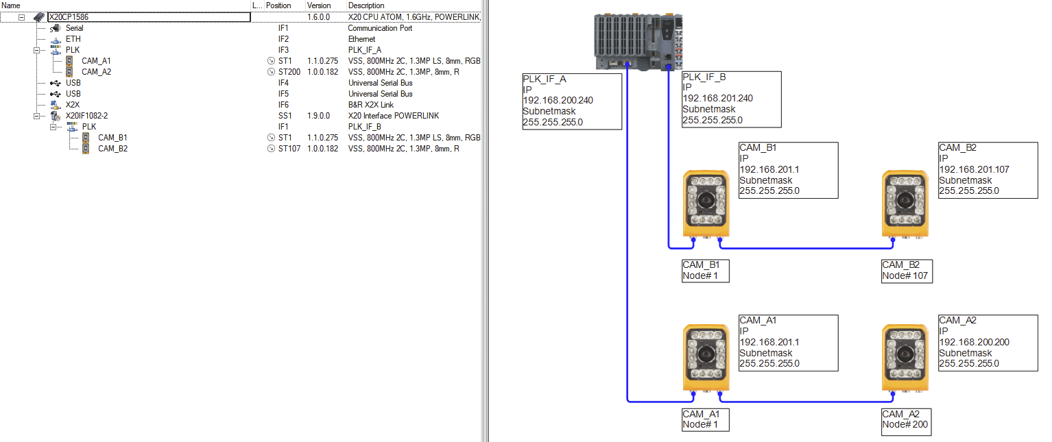
图通过 mapp Vision 分配 POWERLINK 以太网 IP 地址的示例
解决与 POWERLINK 以太网子网中其他网络站点的 IP 地址冲突
如果 POWERLINK 以太网子网中除了摄像机和 PLC 的 POWERLINK 接口外还有其他外部站,则必须遵守以下规定:
即使已根据推荐的 mapp Vision 最佳实践配置了 POWERLINK 以太网,外部站也有可能配置了以摄像机节点编号或 .240 结尾的 IP 地址。在这种情况下,子网中的 IP 通信就会中断,所有摄像机的功能也无法保证。应避免这种情况。
•要解决这类 IP 地址冲突,应考虑以下方案:
•将导致 IP 地址冲突的外部网络站点重新配置为其他空闲的 IP 地址,这些地址不得与 POWERLINK 接口的以太网 IP 地址重合,也不得以摄像机的节点编号为结尾。
偏离 mapp Vision 最佳实践时的注意事项
•如果偏离了推荐的 mapp Vision 最佳实践,则必须确保以下几点,以保证连接到 POWERLINK 接口的摄像机功能正确:
•所有摄像机必须与 POWERLINK 接口位于同一 POWERLINK 以太网子网中。
•子网内不允许有任何 IP 地址冲突。
为确保这一点,必须遵守所述的摄像机 IP 地址和节点编号之间的相关性,必要时还必须使用外部辅助工具(如 http://www.subnet-calculator.com/)。
有关一般 POWERLINK 接口配置的其他详细信息,请参阅以下自动化帮助页面:SG4 的 PLK 接口配置。
Best practices for IP address, subnet mask and node numbers
Information:
The recommended mapp Vision best practice is to assign a POWERLINK Ethernet IP address ending in .240 and a subnet mask of 255.255.255.0 to each POWERLINK interface on which a camera module should be operated.
Explanation:
255.255.255.0 as a subnet mask for POWERLINK Ethernet guarantees that all theoretical POWERLINK stations can receive a unique IP address.
In order for all cameras to communicate with the POWERLINK interface via IP address, each camera as well as the POWERLINK interface itself must have a unique IP address.
The IP address of each camera is automatically assigned by mapp Vision at runtime. This IP address is generated based on the camera node number and the POWERLINK Ethernet IP address of the interface to which the camera is connected. For this purpose, the last byte of the POWERLINK Ethernet IP address of the interface is replaced by the node number of the camera.
For reasons of symmetry, it is recommended to configure the POWERLINK interface in AS with a POWERLINK Ethernet IP address ending in .240.
•Example: Four cameras should be operated on two POWERLINK interfaces on a PLC.
•The two cameras CAM_A1 and CAM_A2 are connected to POWERLINK interface PLK_IF_A; the two cameras CAM_B1 and CAM_B2 are connected to POWERLINK interface PLK_IF_B (see figure below).
•PLK_IF_A is configured with respect to POWERLINK Ethernet with IP address 192.168.200.240 and subnet mask 255.255.255.0. CAM_A1 has node number1; CAM_A2 has node number 200.
•PLK_IF_B is configured with respect to POWERLINK Ethernet with IP address 192.168.201.240 and subnet mask 255.255.255.0. CAM_B1 has node number 1; CAM_B2 has node number 107.
Result: The cameras are automatically assigned the following IP addresses by mapp Vision at runtime: CAM_A1 192.168.200.1, CAM_A2 192.168.200.200, CAM_B1: 192.168.201.1, CAM_B2: 192.168.201.107
Fig.: Example of POWERLINK Ethernet IP address assignment by mapp Vision
Resolving IP address conflicts with other network stations in the POWERLINK Ethernet subnet
The following must be observed if there are other external stations in a POWERLINK Ethernet subnet in addition to the cameras and POWERLINK interface of the PLC:
Even if POWERLINK Ethernet has been configured according to the recommended mapp Vision best practices, it is possible that external stations have been configured with an IP address that ends with the node number of a camera or with .240. In this case, IP communication in the subnet is disrupted and the functionality of all cameras is no longer ensured. This should be avoided.
•The following option should be considered to resolve this type of IP address conflict:
•Reconfigure the external network stations causing the IP address conflict to other, free IP addresses that do not coincide with the Ethernet IP address of the POWERLINK interface or end on the node number of a camera.
To note when deviating from mapp Vision best practices
•If the recommended mapp Vision best practices are deviated from, the following must be ensured for the correct functionality of the cameras connected to the POWERLINK interface:
•All cameras must be in the same POWERLINK Ethernet subnet as the POWERLINK interface.
•Any IP address conflicts within this subnet are not permitted.
To ensure this, the described correlation between IP address and node number of the cameras must be observed and, if necessary, external aids must be used (e.g. http://www.subnet-calculator.com/).
Additional details about the general POWERLINK interface configuration are specified on the following Automation Help page: PLK interface configuration for SG4.