创建输出
输出定义了视觉应用程序在摄像机循环 I/O 接口上的输出1)
图像评估的结果将分配给视觉功能实例的有线输出,因此应用程序可通过 I/O 映射获得这些结果。
视觉功能实例中与应用程序相关的所有参数(循环读取) 都应连接到输出端。在视觉应用中,有线输出是必须的。
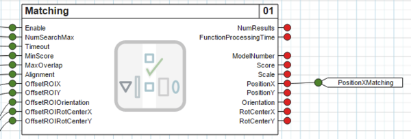
下面以创建输出并将其连接到 <Matching> 的输出 <PositionX> 为例进行说明。
1.可通过拖放将输出从对象目录移动到可视化编辑器的基本区域。
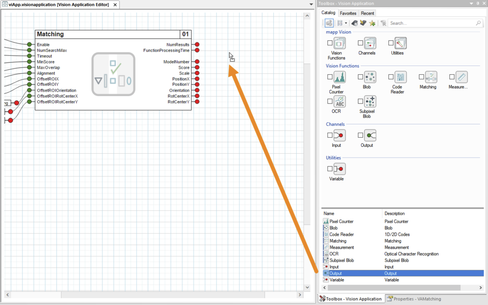
图从对象目录添加输出
2.在属性窗口中调整输出的默认名称,使其易于识别。例如,改为 "PositionXMatching(位置 X 匹配)"。
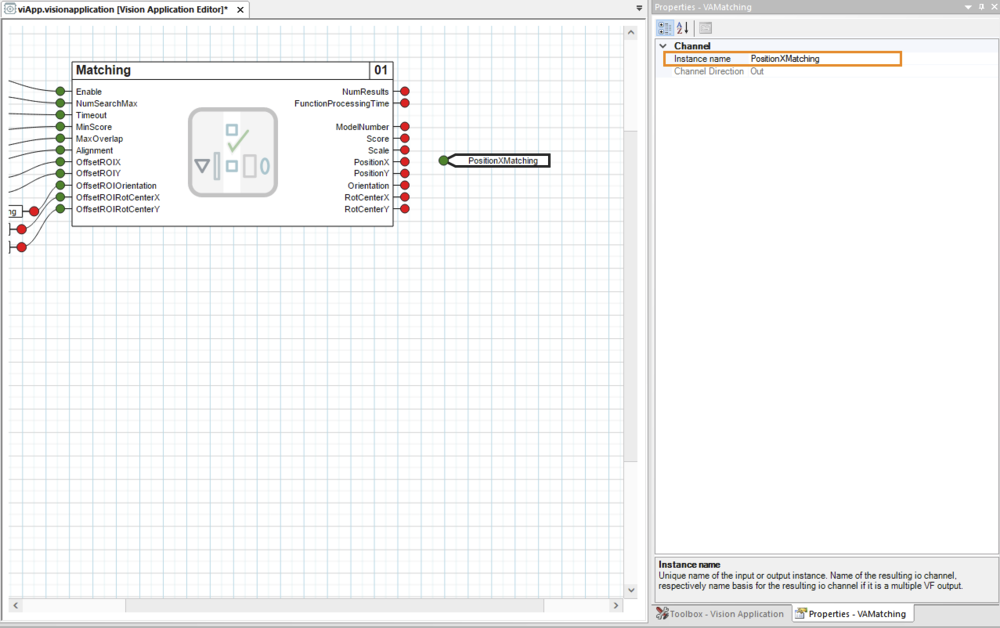
图在属性窗口中重新命名输出
•输出已创建,但尚未与视觉应用程序连接。
连接输出
3.现在要将新创建的输出连接到视觉功能输出。
•为此,首先要将鼠标指针移到视觉功能输出的绿色圆圈上,这样圆圈就会变成绿色方块,鼠标指针也会变成十字形:
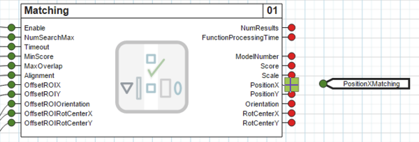
图开始为 <Matching> 的输出 <PositionX> 接线。
•按住鼠标左键,将十字形鼠标指针拖到输出端的红色圆圈上,使圆圈也变成绿色方块。
此时,接线已显示为橙色,但尚未激活。
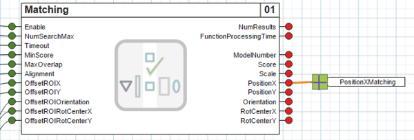
图拖动布线至输出<PositionXMatching>。
•松开鼠标左键后,输出端的绿色圆圈将再次显示。
此外,布线显示为黑色。这表明输出已成功连接到视觉功能,从而连接到视觉应用程序。
图输出 <PositionXMatching> 已成功连接到 <Matching> 的输出 <PositionX>。
有可能接线没有正确拖动到输出端,例如鼠标键释放的时间不正确。这将以红色显示。
在这种情况下,应该用鼠标左键单击布线的自由端,然后按住鼠标左键,将十字形鼠标指针拖动到输出端,直到出现绿色方块。或者,也可以删除布线并再次拖动。
有关布线的更多详情,请参阅 "布线"部分。
数据类型
布线时,输出端将使用视觉函数输出端的数据类型。例如,输出"NumResults "的数据类型为 USINT,因此输出 "NumResultsMatching "在摄像机的 I/O 接口上显示为该数据类型。
有关各视觉功能输出的数据类型,请参阅相应的寄存器概览。
一个输出端只能精确接线一次,即不能多次接线,未连接的输出端会在编译时出错。
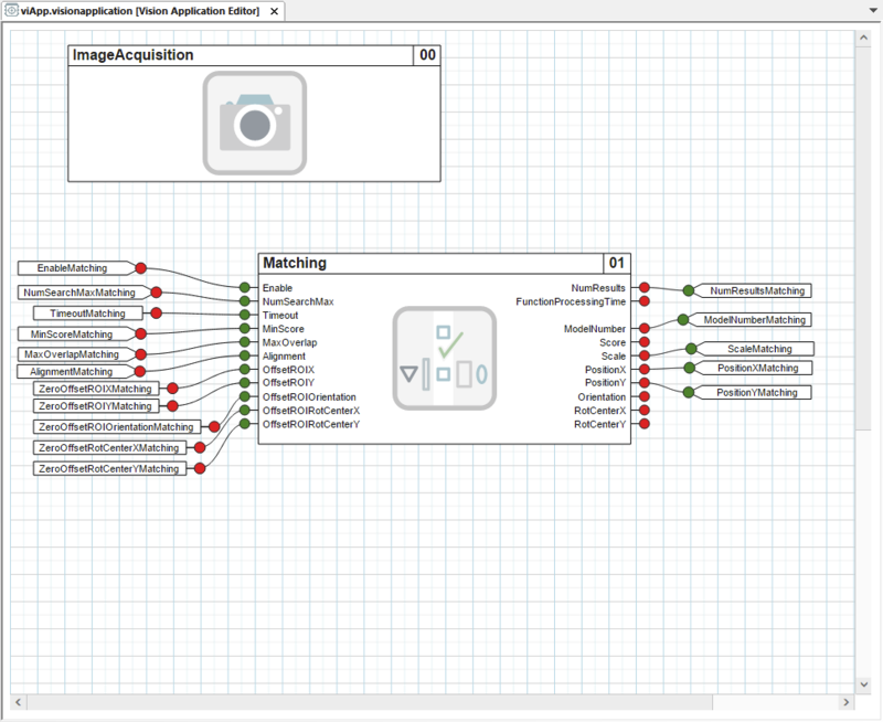
•通过这种方式将视觉功能实例的所有所需输出连接到输出端后,视觉应用程序的 I/O 接口就配置完成了,图像评估也为在 mapp Vision HMI 应用程序中进行配置做好了准备。
图视觉应用程序已完全配置。
1) 只有连接到视觉应用程序视觉功能实例的输出才会应用到摄像机的 I/O 接口。
根据常量 <NumResultsMax> 的设定值,某些输出会出现 n 次(指数为 01、02 等)。
Outputs define the outputs of the vision application at the cyclic I/O interface of the camera.1)
The results of image evaluation are assigned to the wired outputs of a vision function instance and thus available for the application via the I/O mapping.
All parameters (cyclic read) of a vision function instance that are of interest to the application should be wired to an output. A wired output is mandatory in the vision application.
As an example, this describes how to create an output and wire it to output <PositionX> of <Matching>.
•An output is moved from the Object Catalog to the base area of the visual editor using drag-and-drop.
Fig.: Adding an output from the Object Catalog
•The default name of the output is adjusted in the properties window so that it is easily recognizable. For example, to "PositionXMatching".
Fig.: Renaming an output in the properties window
•The output is created but not yet wired to the vision application.
Wiring outputs
•The newly created output is now wired to the vision function output.
•To do this, the mouse pointer is first moved over the green circle of the vision function output so that the circle turns into a green square and the mouse pointer takes on a cross shape:
Fig.: Start wiring output <PositionX> of <Matching>.
•Keeping the left mouse button pressed, the cross-shaped mouse pointer is dragged over the red circle of the output so that the circle also turns into a green square.
The wiring is now already visually indicated in orange, but it is not yet active.
Fig.: Drag the wiring to output <PositionXMatching>.
•After releasing the left mouse button, the green circle of the output is displayed again.
In addition, the wiring is drawn in black. This indicates that the output has been successfully wired to the vision function and thus to the vision application.
Fig.: Output <PositionXMatching> is successfully wired to output <PositionX> of <Matching>.
It it possible that the wiring is not correctly dragged to the output, for example if the mouse button was released at an incorrect time. This is indicated with a red color.
In this case, the free end of the wiring should be clicked with the left mouse button and, keeping the left mouse button pressed, the cross-shaped mouse pointer should be dragged to the output until the green square appears there. Alternatively, the wiring can be deleted and dragged again.
For additional details about wiring, see section Wirings.
Data type
When wired, the output is typed with the data type of the vision function output. For example, output NumResults is of type USINT, and output "NumResultsMatching" therefore appears with this data type at the I/O interface of the camera.
For the data types of the outputs of the respective vision function, see the corresponding register overviews.
An output can only be wired exactly once, i.e. multiple wiring is not possible, and unconnected outputs cause errors during compilation.
•After all desired outputs of the vision function instance have been wired to an output in this way, the I/O interface of the vision application is completely configured and image evaluation is prepared for configuration in the mapp Vision HMI application.
Fig.: The vision application is fully configured.
1) Only outputs that are wired to a vision function instance of the vision application are applied to the I/O interface of the camera.
Depending on the set value of constant <NumResultsMax>, certain outputs occur n times (with indices 01, 02, etc.).