创建输入和变量
输入定义了视觉应用程序在摄像机循环 I/O 接口上的输入1)
运行时在此创建的值将分配给视觉功能实例的有线输入,从而动态影响图像处理。
变量可以为视觉功能实例的有线输入分配值。这些值在设计时确定,运行时无法修改,因此静态地决定图像处理。
视觉功能实例的所有参数(循环写入),如果其值可在运行时通过应用程序中的 I/O 映射进行调整,则必须连接到输入端。所有其他视觉功能输入都可以用变量来代替,以设置一个静态值,并尽可能减少摄像机的 I/O 接口。
下面将举例说明如何创建一个输入和一个变量,然后分别连接到<Matching> 的<Enable> 或<Timeout> 输入。这两个元素的操作步骤类似。
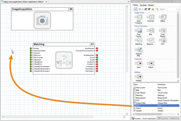
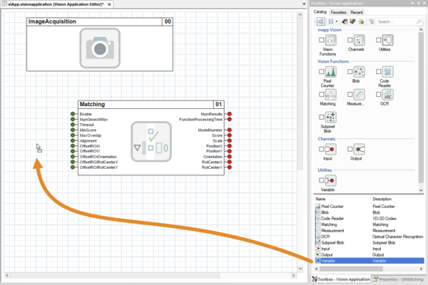
1.输入或变量可通过拖放从对象目录移至可视化编辑器的基本区域。
图从对象目录添加输入 |
图:从对象目录添加变量 |
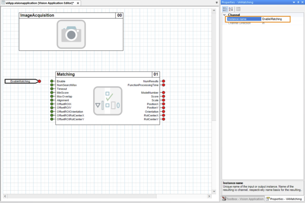
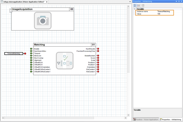
2.输入或变量的默认名称可在属性窗口中调整,以便于识别。例如,"EnableMatching(启用匹配)"或 "TimeoutMatching(超时匹配)"。
对于变量,字段 <Value> 中的默认值会被调整。例如,调整为 "100"。
图在属性窗口中重新命名输入 |
图在属性窗口中重命名变量并赋值 |
输入或变量已创建,但尚未与视觉应用程序连接。
连接输入和变量
3.现在,每个新创建的输入端或变量都要与视觉功能输入端连线。
•为此,首先要将鼠标指针移到输入或变量的红色圆圈上,这样圆圈就会变成绿色方块,鼠标指针也会变成十字形:
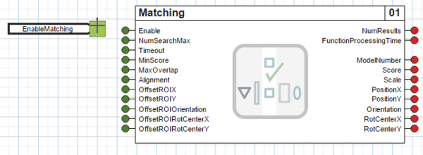
图开始连接输入<EnableMatching>。 |
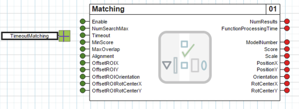
图开始为变量 <TimeoutMatching> 布线。 |

•按住鼠标左键,将十字形鼠标指针拖到视觉功能输入的红色圆圈上,使圆圈也变成绿色方块。
此时,接线已经以橙色显示,但尚未激活。
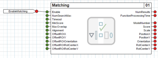
图从输入<EnableMatching>拖动布线到 <Matching> 的输入<Enable>。 |
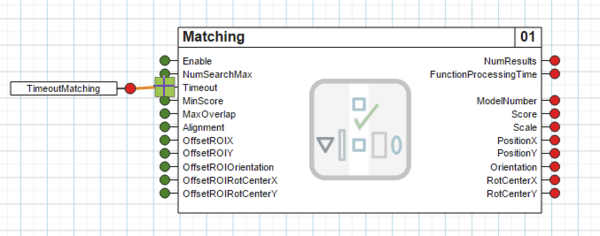
图从变量 <TimeoutMatching> 拖动接线到 <Matching> 的输入<Timeout>。 |
•松开鼠标左键后,将再次显示视觉功能输入端的绿色圆圈。
此外,布线会显示为黑色。这表明输入或变量已成功连接到视觉功能,从而连接到视觉应用程序。
图输入 <EnableMatching> 已成功连接到 <Matching> 的输入 <Enable>。 |
图变量 <TimeoutMatching> 已成功连接到 <Matching> 的输入 <Timeout>。 |
例如,如果在不正确的时间松开了鼠标按钮,就有可能没有正确地将接线拖到视觉功能输入端。这种情况会以红色显示。
在这种情况下,应单击布线的自由端,然后按住鼠标左键,将十字形鼠标指针拖动到视觉功能输入端,直到出现绿色方块。或者,也可以删除布线并再次拖动。
有关布线的更多详情,请参阅 "布线"部分。
数据类型和多重布线
布线时,输入或变量的类型与视觉功能输入的数据类型相同。在示例中,输入 <EnableMatching> 的类型为 BOOL,并以这种数据类型出现在摄像机的 I/O 接口上。变量 <TimeoutMatching> 的类型为 UINT。
有关各视觉功能输入端的数据类型,请参阅相应的寄存器概览。
输入或变量不能与同一视觉功能实例的其他输入连接。
但如果输入的数据类型相同,则可以与其他视觉功能实例的输入连接。这里的视觉功能实例可以是不同类型的(匹配、读码等)。所有连接到同一输入或变量的视觉功能输入都会分配相同的值。具有多个视觉功能的视觉应用程序只能在机器视觉智能相机上运行,而不能在机器视觉智能传感器上运行。
不允许将视觉功能实例的输入端与两个输入端、两个变量或一个输入端和一个变量进行多重布线。
不允许的布线用红色表示。在属性窗口中,当选择布线时,<布线错误/错误信息>上会出现提示。
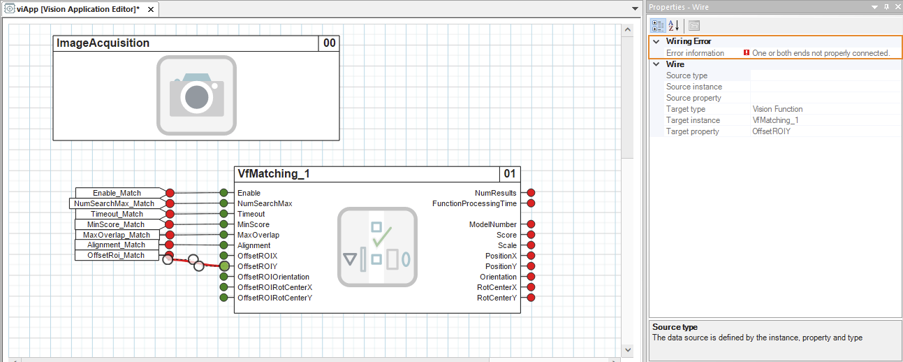
图无效的多重布线
•通过这种方式将所有视觉功能输入端与变量或输入端成功布线后,视觉应用程序的输入端就完全配置好了。

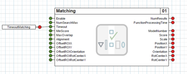
图匹配的所有输入均已布线。
1) 只有连接到视觉应用程序的视觉功能实例的输入才会应用到摄像机的 I/O 接口。
Inputs define the inputs of the vision application at the cyclic I/O interface of the camera.1)
The values created there at runtime are assigned to the wired inputs of a vision function instance and thus dynamically influence image processing.
Variables make it possible to assign values to the wired inputs of a vision function instance. These values are determined at design time, cannot be modified at runtime and thus statically determine the image processing.
All parameters (cyclic write) of a vision function instance whose values should be adjustable via I/O mapping in the application at runtime must be wired to an input. All other vision function inputs can be wired with a variable instead to set a static value and keep the I/O interface of the camera as small as possible.
As an example, this describes how to create an input and a variable that are then wired to input <Enable> or <Timeout> of <Matching>, respectively. The procedure is similar for both elements.
1.An input or variable is moved from the Object Catalog to the base area of the visual editor using drag-and-drop.
Fig.: Adding an input from the Object Catalog |
Fig.: Adding a variable from the Object Catalog |
2.The default name of the input or variable is adjusted in the properties window so that is easily recognizable. For example, to "EnableMatching" or "TimeoutMatching".
For variables, the default value in field <Value> is adjusted. For example, to "100".
Fig.: Renaming an input in the properties window |
Fig.: Renaming a variable and assigning a value in the properties window |
The input or variable is created but not yet wired to the vision application.
Wiring inputs and variables
3.Each newly created input or variable is now wired to a vision function input.
•To do this, the mouse pointer is first moved over the red circle of the input or variable so that the circle turns into a green square and the mouse pointer takes on a cross shape:
Fig.: Start wiring input <EnableMatching>. |
Fig.: Start wiring variable <TimeoutMatching>. |
•Keeping the left mouse button pressed, the cross-shaped mouse pointer is dragged over the red circle of the vision function input so that the circle also turns into a green square.
The wiring is now already visually indicated in orange, but it is not yet active.
Fig.: Drag the wiring from input <EnableMatching> to input <Enable> of <Matching>. |
Fig.: Drag the wiring from variable <TimeoutMatching> input <Timeout> of <Matching>. |
•After releasing the left mouse button, the green circle of the vision function input is displayed again.
In addition, the wiring is drawn in black. This indicates that the input or variable has been successfully wired to the vision function and thus to the vision application.
Fig.: Input <EnableMatching> is successfully wired to input <Enable> of <Matching>. |
Fig.: Variable <TimeoutMatching> is successfully wired to input <Timeout> of <Matching>. |
It it possible that the wiring is not correctly dragged to the vision function input, for example if the mouse button was released at an incorrect time. This is indicated with a red color.
In this case, the free end of the wiring should be clicked and, keeping the left mouse button pressed, the cross-shaped mouse pointer should be dragged to the vision function input until the green square appears there. Alternatively, the wiring can be deleted and dragged again.
For additional details about wiring, see section Wirings.
Data type and multiple wiring
When wired, the input or variable is typed with the data type of the vision function input. In the example, input <EnableMatching> is of type BOOL and appears with this data type on the I/O interface of the camera. Variable <TimeoutMatching> is of type UINT.
For the data types of the inputs of the respective vision functions, see the corresponding register overviews.
The input or variable cannot be wired to other inputs of the same vision function instance.
However, wiring with inputs of other vision function instances is possible, provided that the inputs have identical data types. The vision function instances can be of different types here (Matching, Code Reader, etc.). All vision function inputs wired to the same input or variable are assigned identical values. A vision application with multiple vision functions can only be run on a machine vision Smart Camera, not on a machine vision Smart Sensor.
Multiple wiring of an input of a vision function instance with two inputs, two variables or with one input and one variable is not permitted.
Impermissible wiring is indicated with a red color. In the properties window, a note appears on <Wiring error / Error info> when the wiring is selected.
Fig.: Invalid multiple wiring
•After all vision function inputs have been successfully wired to a variable or an input in this way, the input of the vision application is completely configured.
Fig.: All inputs of Matching have been wired.
1) Only inputs that are wired to a vision function instance of the vision application are applied to the I/O interface of the camera.