为了在准确的时间点触发图像采集,必须预先计算出所需位置的正确 NetTime,并满足某些条件。
例如,带有摄像头和外部光棒的 CPU 应与 B&R 驱动技术产品组合中的组件同步。
•必须使用 POWERLINK NetTime 来触发摄像头和外部光源。
•为了准确地触发到要检查的物体到达摄像机的轴位置,必须考虑 POWERLINK 响应时间、拓扑结构和轴的速度/加速度来计算 NetTime。
•要准确触发相机,必须使用过程变量DelayNetTime(n)指定 POWERLINKNetTime,并使用图像采集(ImageAcquisition)进行触发。
信息:
有关 POWERLINK 周期时间和输出延迟的其他信息,请参阅POWERLINK - 输出延迟 - 默认设置(通信 → POWERLINK → 响应时间 → 输出延迟)部分。
一般情况下必须遵守本节(通信 → POWERLINK → 响应时间)。
条件
使用 NetTime 触发时必须注意以下几点:
•POWERLINK 周期必须与任务类同步。
•对于 CPU 计时,POWERLINK 必须配置为 "系统计时器 "接口。
•必须考虑 POWERLINK 的响应时间,以便能够计算出足够长的未来时间(参见自动化帮助:通信 → EPL → 响应时间)
•考虑 POWERLINK 拓扑结构。
•每 100 m 铜缆/光缆每个方向 1 µs
•考虑到每个集线器层约 2 µs。
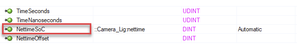
•使用相应 POWERLINK 接口的 NettimeSoC 数据点确定管理节点 (MN) 的 NetTime。需要注意的是,NetTime 值总是过去的一个周期。
•如果系统刻度与 POWERLINK MN 接口同步,且任务时间与 POWERLINK 周期时间相同,则过去的周期数一般为 4。
•将数据从 POWERLINK 周期复制到摄像头的中断必须在最后一个 SoC 之前 100 µs 知道。这意味着,在正常情况下,从从 MN 获取 NetTime 到在摄像机上做出响应最多需要 4 个周期 + 1 个周期,因为 NettimeSoC 的时间已经过去了一个周期。
•摄像机和灯光必须使用 ParID 与 ACOPOS 驱动元件同步(参见自动化帮助):运动控制 → ACP10/ARNC0 → 参考手册 → ACP10 → ACOPOS 参数 ID),以实现更精确的 NetTime 计算。
•对于智能灯,原则上与智能摄像机相同,只是智能灯模块需要多半个 X2X 周期(摄像机的 X2X 周期始终与 POWERLINK 周期时间相同)。
应用示例
•转台应用有 8 个等分区域(即每个区域一个 45°)。
•8 个区域中的每个区域都有不同的数据代码。
•通过圆心点的驱动轴以 800 rpm 的速度旋转圆盘。
•为了获取 45° 位置处的代码图像,需要事先读出目标的当前位置 + POWERLINK NetTime + 目标的速度(例如在 35° 位置处)。
•利用这些变量可以精确地预先计算出 NetTime 到达 45° 位置时的触发瞬间:结果 = (45° - 当前位置) /速度。
•然后根据结果增加 POWERLINK NetTime,以便在所需位置触发图像采集。
信息:
由于当前位置和当前 NetTime 并不完全同步,因此必须在此基础上增加一个小偏移量。
输入和输出数据的定时
经过验证的简单公式
智能灯响应时间
•四舍五入为网络周期时间的整数倍:
最小响应时间 = 任务时间 + 5 * PLK 时间
信息:
如果智能灯的网络时间已过,则会立即闪烁。
在 5 * PLK 时间和 ExposureTime = 20 的情况下,光圈在闪烁时已再次关闭,因此图像为黑色。在曝光时间 = 100 的情况下,当闪光灯闪烁太晚时,快门仍会轻微打开,从而导致图像曝光不足。
智能相机响应时间
•四舍五入为网络周期时间的整数倍:
最小响应时间 = 任务时间 + 4 * PLK 时间
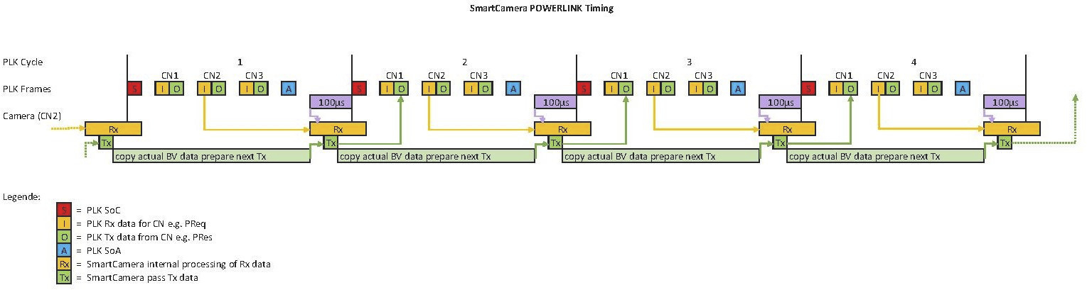
计时
当前周期的 Rx 数据评估或下一个 POWERLINK 周期的 Tx 数据释放在下一个 SoC 之前 100 µs 进行。当前 Tx 帧传输到下一个周期的 POWERLINK 网络后,POWERLINK Tx 帧为下一个 POWERLINK 周期做好准备(FPGA 因此有一个 POWERLINK 周期可用于处理)。
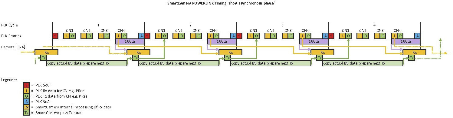
注意事项
需要注意的是,在中断请求(SoC 之前 100 µs)之后收到的 Rx 数据将在下一个 POWERLINK 周期中进行评估。如果 POWERLINK 周期的异步阶段少于 100 µs,且智能相机是受控节点,仅在周期结束时由管理节点查询,则有时会出现这种情况。
本节主题
In order to trigger the image acquisition at an exact point in time, the correct NetTime for the required position must be precalculated and certain conditions must be met.
As an example, a CPU with a camera and external light bar should be synchronized with components from the B&R drive technology portfolio.
•The POWERLINK NetTime must be used to trigger the camera and the external light.
•In order to trigger to the exact axis position at which the object to be examined arrives on the camera, NetTime must be calculated by taking into account the POWERLINK response time, topology and speed/acceleration of the axis.
•To trigger the camera exactly, the POWERLINK NetTime must be specified with process variable DelayNetTime(n) and triggered with ImageAcquisition.
Information:
For additional information about POWERLINK cycle times and output latencies, see section POWERLINK - Output latency - Default settings (Communication → POWERLINK → Response time → Output latency) .
This section (Communication → POWERLINK → Response time) must be observed in general.
Conditions
The following points must be taken into account for triggering with NetTime:
•The POWERLINK cycle must be synchronous to the task class.
•For the CPU timing, POWERLINK must be configured as the "System timer" interface.
•The POWERLINK response time must be taken into account in order to be able to calculate far enough into the future (see Automation Help: Communication → EPL → Response time)
•Take the POWERLINK topology into account.
•1 µs per 100 m copper / fiber optic cable per direction
•Take into account approx. 2 µs per hub level.
•Determine NetTime of the managing node (MN) using data point NettimeSoC of the corresponding POWERLINK interface. It is important to note that the NetTime value is always one cycle in the past.
•The number of cycles in the past is generally 4, provided that the system tick is synchronized with the POWERLINK MN interface and the task has the same time as the POWERLINK cycle time.
•The interrupt to copy the data from the POWERLINK cycle to the camera must be known 100 µs before the last SoC. This means that with normal behavior, the time from retrieving the NetTime from the MN to the response on the camera takes a maximum of 4 cycles + 1 cycle since the time from the NettimeSoC is already one cycle in the past.
•The camera and light must be synchronized with ACOPOS drive components using the ParIDs (see Automation Help: Motion control → ACP10/ARNC0 → Reference manual → ACP10 → ACOPOS parameter IDs) to enable an even more exact NetTime calculation.
•With a Smart Light, the same behavior as with a Smart Camera applies in principle, except that the Smart Light module needs half an X2X cycle longer (the X2X cycle in the camera is always the same value as the POWERLINK cycle time).
Application example
•A turntable application with 8 equally divided areas (i.e. one 45° section each).
•A different data code is applied in each of the 8 areas.
•The drive axis through the center point of the circle rotates the disc at 800 rpm.
•In order to acquire a code image at position 45°, the current position of the target + POWERLINK NetTime + speed of the target is read out beforehand (e.g. at position 35°).
•The trigger instant at which NetTime reaches position 45° can be precisely precalculated using these variables: Result = (45° - Current position) /Speed.
•Then increase the POWERLINK NetTime by the result in order to trigger the image acquisition at the desired position.
Information:
Since the current position and current NetTime are not completely synchronous, a small offset must be added to this.
Timing of input and output data
Proven simple formulas
Smart Light response time
•Round up to integer multiples of the network cycle time:
Min. response time = Task time + 5 * PLK time
Information:
If the NetTime is in the past for the Smart Light, it blinks immediately.
With 5 * PLK time and ExposureTime = 20, the aperture is therefore already closed again when flashing and the image is therefore black. With ExposureTime = 100, the shutter is still slightly open when the flash is too late, resulting in a somewhat underexposed image.
Smart Camera response time
•Round up to integer multiples of the network cycle time:
Min. response time = Task time + 4 * PLK time
Timing
Evaluation of the Rx data of the current cycle or release of the Tx data for the next POWERLINK cycle takes place 100 µs before the next SoC. After the current Tx frame has been transferred to the POWERLINK network for the next cycle, the POWERLINK Tx frame is prepared for the POWERLINK cycle after next (the FPGA thus has one POWERLINK cycle available for processing).
Note
It is important to note that Rx data coming after the interrupt request (100 µs before the SoC) will be evaluated in the next POWERLINK cycle. This is sometimes the case if the asynchronous phase of the POWERLINK cycle is less than 100 µs and the Smart Camera is a controlled node that is only queried by the managing node at the end of the cycle.