信息:
本节中指定的参数是硬件模块配置的一部分,可通过 Automation Studio 访问。
信息:
决定 POWERLINK 帧长度的个别配置参数只能在 Automation Studio 配置过程中更改(即非循环)。因此,这些参数只能在运行时读取,并标识为常量。
USINT |
1 to 10 |
图像采集次数 |
|
W |
|
BOOL |
0 or 1 |
切换线路传感器模式 |
|
W |
|
配置参数 |
|||||
BOOL |
0 or 1 |
切换触发源(软件/硬件) |
|
W |
|
BOOL |
0 or 1 |
切换触发延迟类型 |
|
W |
|
BOOL |
0 or 1 |
切换触发数字输入的边缘方向 |
|
W |
|
BOOL |
0 or 1 |
启用/禁用传感器 x 轴的镜像功能 |
|
W |
|
BOOL |
0 or 1 |
启用/禁用传感器 Y 轴镜像 |
|
W |
|
BOOL |
0 or 1 |
启用/禁用 2x2 分档 |
|
W |
|
BOOL |
0 or 1 |
启用/禁用子采样 |
|
W |
|
ImageWidth (area-based) LineWidth (line-based) |
UINT |
1 to sensor width |
以像素为单位设置要采集图像的宽度 |
|
W |
ImageHeight (area-based) LineHeight (line-based) |
UINT |
1 to sensor height |
以像素为单位设置要获取图像的高度 |
|
W |
ImageOffsetX (area-based) LineOffsetX (line-based) |
UINT |
0 to sensor width - 1 |
对于要获取的图像 以像素为单位设置 x 轴的偏移量 |
|
W |
ImageOffsetY (area-based) LineOffsetY (line-based) |
UINT |
0 to sensor height - 1 |
对于要获取的图像: 以像素为单位设置 Y 轴的偏移量 |
|
W |
BOOL |
0 or 1 |
启用/禁用线性传感器模式 |
|
W |
|
UINT |
1 to 4096 |
线性传感器模式下的图像采集次数 |
|
W |
|
UDINT |
1 to 4,294,967,295 |
线性传感器模式下两幅图像之间的时间间隔(以 ns 为单位) |
|
W |
|
USINT |
0 to 2 |
设置焦点缩放 0 = 步(原始数据) 1 = 毫米 2 = 10 µm(默认值) |
|
W |
|
BOOL |
0 or 1 |
启用/禁用渐晕校正 |
|
W |
|
BOOL |
0 or 1 |
启用/禁用 LED 温漂校正 |
|
W |
|
常数
MultiCapture/多重捕捉
用于多幅图像采集的参数。指定图像处理开始前一个周期内要采集的图像数量。
只要参数 MultiCapture = 1,就会使用索引为 01 的参数。否则,将逐个处理参数集,直到达到触发边沿时有效的 MultiCapture 值为止。
每个图像都会收到一个时间戳。指定第一幅图像的 ImageNettime 时间,以便在视觉应用程序的视觉功能中进行进一步处理。
信息:
对于需要采集多幅图像的视觉功能,必须确保应用程序中提供所需的最少图像数量。这可以通过使用 MultiCapture 或在视觉应用程序中进行图像处理来设置。
触发多次图像采集
根据触发源(TriggerSource)和触发延迟(TriggerDelay)的不同,激活触发器以获取多 幅图像的可能顺序如下。
配置参数: |
设置 TriggerSource、n x "延迟"、DelayNetTime、ExposureTime、FlashSegment 和 FlashColor。必须启用数字输入。 |
启动序列: |
通过设置 ImageAcquisition 和触发输入的一个边沿 |
序列: |
•将设置 AcquisitionCount 乘以下一次图像采集的内部时基。 •不检查小于 31 位的限制。 •如果延迟时间太小,以至于在当前采集完成之前就触发了下一次采集(曝光时间 + 触发传感器 + 超时),则会输出错误信息,并延迟摄像机直到完成图像采集。FailedAcquisitionCnt 会递增。由于该状态必须由 FPGA 检查,并且只能在当前图像采集创建之前立即识别,因此无法提前中止图像采集周期。因此,必须清除为图像采集序列预留的内存。 |
|
|
|---|---|
配置参数: |
设置触发源、n x "延时"、延时网络时间、曝光时间、闪光段和闪光颜色。 |
启动序列: |
通过图像采集设置 |
序列: |
•为下一次图像采集设置内部时基的 MultiCapture 时间。 •不检查小于 31 位的限制。 •如果延迟太小,以至于在当前采集完成之前触发了第 n 次采集(延迟-n > 曝光时间-n-1 + 触发传感器 + 开销),则会输出错误信息并延迟摄像机直到完成图像采集。FailedAcquisitionCnt 会递增。由于该状态必须由 FPGA 检查,并且只能在当前图像采集之前识别,因此无法提前中止图像采集序列。因此,必须清除为图像采集序列预留的内存。 |
|
|
|---|---|
配置参数: |
设置触发源、n x NetTime 与 DelayNetTime、ExposureTime、FlashSegment 和 FlashColor。 |
启动序列: |
通过图像采集设置 |
序列: |
•多重捕捉时间为下一次图像捕捉设置 NetTime。这意味着下一个净时间必须总是在未来。如果净时间超过 10 秒,则图像处理周期会出错中止。 •如果与下一个 NetTime 之间的差值小于当前图像采集的持续时间(曝光时间 + 触发传感器 + 开销),则会输出错误并延迟摄像机直到图像采集序列完成。FailedAcquisitionCnt 会递增。由于该状态必须由 FPGA 检查,并且只能在当前图像采集之前识别,因此无法提前中止图像采集序列。因此,必须清除为图像采集序列预留的内存。 |
LinesensorMode/线传感器模式
用于在 线传感器模式下选择运行方式(模式)的参数。.
值 |
信息 |
|
|---|---|---|
BOOL |
0 |
静态行传感器(LinesPerImage、 LineScanPeriod)。 |
1 |
动态(循环)线路传感器。(CyclicLineScanNettime, CyclicLineScanPeriod) |
静态线路传感器:
如果激活此模式,则通过图像采集触发行传感器图像。每次图像采集的图像与以下设置相对应: 线宽(LineWidth)、线高(LineHeight)、线偏移量(LineOffsetX)、线偏移量(LineOffsetY)、每图像行数(LinesPerImage)、线扫描周期(LineScanPeriod),且不能在运行时更改。
该模式在无速度变化时使用。
动态线路传感器
如果激活了该模式,则会通过图像采集(ImageAcquisition)触发线性传感器图像,并可在运行期间使用参数 CyclicLineScanNettime 和 CyclicLineScanPeriod(除了上述静态线性传感器的参数外)进行周期性调整。
该模式用于加速或速度变化时。通过 CyclicLineScanNettime 可以传输新的 CyclicLineScanPeriod,在图像采集期间也是如此。
TriggerSource
用于选择触发源的参数。触发通过参数 TriggerDelay(软件触发)或 TriggerEdge(硬件触发)进行,具体取决于该选择。
TriggerDelay
值 |
信息 |
|
|---|---|---|
BOOL |
0 |
参数 DelayNetTime(n)中设置的时间用于触发延迟。 |
1 |
达到 NetTime 时,触发器被激活。 |
信息:
如果在 TriggerSource(触发源)中选择了通过数字输入进行硬件触发,那么在 TriggerDelay(触发延时)中只需选择延时即可。
TriggerEdge
水平翻转图像
绕 Y 轴镜像。反转传感器 x 轴(传感器宽度)上的像素顺序。
应用翻转图像参数
信息:
不建议在行传感器模式下使用翻转图像参数,因为这样只会返回碎片图像。
Flip image vertically
围绕 x 轴镜像。反转传感器 y 轴(传感器高度)上的像素顺序。
另请参阅应用翻转图像参数。 .
Binning
参数的可用性取决于所使用的传感器。
分档是指对相邻像素进行分组(形成像素块)。具体来说,该参数在图像采集过程中从 2x2 像素中创建一个(虚拟)像素。使用该参数的前提条件是所使用的图像传感器支持二进制。
启用二进制后,将为该虚拟像素计算出一个虚拟的、更高的感光度,从而减少噪点。传感器的读出速度也会加快。不过,图像分辨率会降低(由于合并了像素)。
分档是 PixelConfiguration 的一部分,因此不能与参数 "子采样 "一起激活。.
信息:
激活此参数后,图像的最大高度和最大宽度将减半。在应用 ImageWidth、ImageHeight、ImageOffsetX 和 ImageOffsetY 参数时,必须注意缩小的图像尺寸。
Subsampling
参数的可用性取决于所使用的传感器。
使用子采样时,并非每个像素都会被读出(基本上降低了采样率)。具体来说,使用该参数时,只读出每第二个像素(水平和垂直方向)。
启用子采样后,传感器的读取速率会因图像数据的减少而加快。但图像分辨率会降低。
噪声不会受到子采样的影响。
信息:
子采样是 PixelConfiguration 的一部分,因此不能与参数 Binning 一起激活。
信息:
激活此参数后,图像的最大高度和最大宽度将减半。在应用 ImageWidth、ImageHeight、ImageOffsetX 和 ImageOffsetY 参数时,必须注意缩小的图像尺寸。
ImageWidth
如果需要减小采集图像的尺寸,可以使用参数 ImageWidth 来减小图像的最大宽度。这样可以加快图像采集速度,缩短图像处理时间。
有关该参数与其他图像采集配置参数的关系,请参阅图像部分 - 参数。
信息:
对于 130 万像素传感器以及 350 万像素和 530 万像素传感器,该值将四舍五入为可被 32 整除的值。
ImageWidth 会自动四舍五入到下一个可整除的值(例如:输入 790 会四舍五入到 800),但会根据传感器将其限制在允许的图像区域内。ImageOffsetX 会相应减小,以确保至少获取配置的图像区域。另请参阅图像裁剪 - 参数调整。
ImageHeight
如果需要减小采集图像的尺寸,可以使用参数 ImageHeight 来减小图像的最大高度。这样可以加快图像采集速度,缩短图像处理时间。
有关该参数与其他图像采集配置参数的关系,请参阅图像部分 - 参数。
线性传感器模式:
启用线性传感器模式后(参见线性传感器),该参数将定义切口高度。
如果配置的线少于 16 条,则必须使用位图格式,而不是用于在 mapp Vision HMI 应用程序中显示采集图像的 JPEG 格式。
信息:
该值直接适用于 130 万像素传感器以及 350 万像素和 530 万像素传感器。
ImageOffsetX
如果获取图像的宽度减小,则可定义图像在传感器上的位置偏移。ImageOffsetX 不能大于 WidthMax - ImageWidth。偏移仅限于此最大值。
有关该参数与其他图像采集配置参数的关系,请参阅图像部分 - 参数。
信息:
对于 130 万像素传感器以及 350 万像素和 530 万像素传感器,该值向下舍入为可被 32 整除的值。
ImageOffsetY
如果获取的图像高度降低,则可以为图像在传感器上的位置定义一个偏移量。ImageOffsetY 不能大于 HeightMax - ImageHeight。偏移仅限于此最大值。
有关该参数与其他图像采集配置参数的关系,请参阅图像部分 - 参数。
信息:
该值直接适用于 130 万像素传感器以及 350 万像素和 530 万像素传感器。
Line sensor
参数的可用性取决于所使用的传感器。
用于启用线条传感器模式的参数。线的高度由参数 ImageHeight 定义。其他相关参数仅在行传感器模式下有效。
信息
在线性传感器模式下,可以使用内部照明(使光脉冲与图像采集同步)或外部连续照明。
LinesPerImage
参数的可用性取决于所使用的传感器。
静态行传感器模式下的图像获取次数或最大行传感器高度:
130 万像素传感器的最大行传感器高度为 4096,行宽度为 1280。
因此,配置的图像高度(ImageHeight)与每图像行数(LinesPerImage)的乘积不允许超过 4096。因此,单行采集(ImageHeight = 1)可配置 4096 次图像采集。如果增加 ImageHeight(例如 1024),则必须相应减少 LinesPerImage(例如 4)。
使用较大的图像传感器时,也必须降低 LinesPerImage。530 万像素传感器的最大线传感器高度为 2048,线宽为 2592。
信息:
350 万像素传感器不能用作线性传感器!
LineScanPeriod
该参数的可用性取决于所使用的传感器。
在静态线条传感器模式下,通过 LinesPerImage 配置的图像采集间隔时间长度。
值 |
信息 |
|
|---|---|---|
UDINT |
1 to 4,294,967,295 |
在线性传感器模式下,两次图像采集之间的时间间隔为 1 ns 至 4.29 s,增量为 1 ns。 虽然两幅图像之间的时间可以从 1 ns 开始配置,但根据图像传感器和图像采集参数的不同,会有一个下限。 最大行频(1280 像素的整行): 16 千赫 |
在选择两幅图像之间的延迟时间时,必须考虑图像采集时间和传感器的积分时间(ExposureTime(n))。
因此,对于 130 万像素的传感器,在时间大于 31 µs 时,必须将差值(曝光时间 - 31.7 µs)加到允许的线路扫描周期上。
根据线条高度和分档,等待时间的数值如下:
停用分档 |
启用分档 |
|
|---|---|---|
1280 x 1 |
68 µs |
63 µs |
1280 x 2 |
74 µs |
67 µs |
1280 x 4 |
85 µs |
76 µs |
1280 x 1024 |
5714 µs |
4466 µs |
对于 530 万像素传感器,如果时间大于 29 µs,则必须将差值(ExposureTime - 29.8 µs)加到允许的线条扫描周期上。
根据线条高度和分档,等待时间的值如下:
停用分档 |
启用分档 |
|
|---|---|---|
2592 x 1 |
319.3 µs |
364.9 µs |
2592 x 2 |
364.9 µs |
364.9 µs |
2592 x 4 |
364.9 µs |
410.5 µs |
2592 x 8 |
410.5 µs |
501.7 µs |
FocusScale
可从生产日期 1951(年/日历周)开始在摄像机端使用。
毫米 "和 "10 微米 "由制造商统一设置。这可确保在维修期间更换摄像机硬件时无需再次调整新摄像机的焦距。
VignettingCorrection
可通过此参数启用自动修正功能。
从生产日期 2103(年/日历周)开始在摄像机端可用。
LEDTempDriftCorrection
从生产日期 2103(年/日历周)开始在摄像机端可用。
LED 的强度会相互调整。因此,启用 LEDTempDriftCorrection 后,光输出会略微减少。曝光时间也会随之增加。
The parameters specified in this section are part of the hardware module configuration that can be accessed via Automation Studio.
Individual configuration parameters that determine the length of a POWERLINK frame can only be changed during configuration in Automation Studio (i.e. acyclically). These parameters can therefore only be read at runtime and are identified as constants.
USINT |
1 to 10 |
Number of image acquisitions |
|
W |
|
BOOL |
0 or 1 |
Switches the line sensor mode |
|
W |
|
Configuration parameters |
|||||
BOOL |
0 or 1 |
Switches the source of the trigger (software/hardware) |
|
W |
|
BOOL |
0 or 1 |
Switches the type of trigger delay |
|
W |
|
BOOL |
0 or 1 |
Switches the edge direction at the digital input for triggering |
|
W |
|
BOOL |
0 or 1 |
Enables/Disables mirroring of the x-axis of the sensor |
|
W |
|
BOOL |
0 or 1 |
Enables/Disables mirroring of the y-axis of the sensor |
|
W |
|
BOOL |
0 or 1 |
Enables/Disables 2x2 binning |
|
W |
|
BOOL |
0 or 1 |
Enables/Disables subsampling |
|
W |
|
ImageWidth (area-based) LineWidth (line-based) |
UINT |
1 to sensor width |
Sets the width of the image to be acquired in pixels |
|
W |
ImageHeight (area-based) LineHeight (line-based) |
UINT |
1 to sensor height |
Sets the height of the image to be acquired in pixels |
|
W |
ImageOffsetX (area-based) LineOffsetX (line-based) |
UINT |
0 to sensor width - 1 |
For the image to be acquired: Sets the offset on the x-axis in pixels |
|
W |
ImageOffsetY (area-based) LineOffsetY (line-based) |
UINT |
0 to sensor height - 1 |
For the image to be acquired: Sets the offset on the y-axis in pixels |
|
W |
BOOL |
0 or 1 |
Enables/Disables line sensor mode |
|
W |
|
UINT |
1 to 4096 |
Number of image acquisitions in line sensor mode |
|
W |
|
UDINT |
1 to 4,294,967,295 |
Time between 2 images in line sensor mode in ns |
|
W |
|
USINT |
0 to 2 |
Sets the focus scaling 0 = Steps (raw data) 1 = mm 2 = 10 µm (default) |
|
W |
|
BOOL |
0 or 1 |
Enables/Disables vignetting correction |
|
W |
|
BOOL |
0 or 1 |
Enables/Disables LED temperature drift correction |
|
W |
|
Constants
MultiCapture
Parameter for multiple image acquisitions. Specifies the number of images to be acquired in a cycle before image processing starts.
As long as parameter MultiCapture = 1, the parameters with index 01 are used. Otherwise, the parameter sets are processed one after the other until the value of MultiCapture valid at the time of the trigger edge is reached.
Each individual image receives a timestamp. ImageNettime of the first image is specified for further processing in a vision function within a vision application.
Information:
For vision functions that require multiple image acquisitions, it is important to ensure that the required minimum number of images are available in the application. This can be done by setting the number using MultiCapture or by image processing within a vision application.
Triggering multiple image acquisitions
The following possible sequences result for activating the triggers for multiple image acquisition depending on TriggerSource and TriggerDelay.
Configuring the parameters: |
Set TriggerSource, n x "Delay" with DelayNetTime, ExposureTime, FlashSegment and FlashColor. Digital input must be enabled. |
Starting the sequence: |
By setting ImageAcquisition and an edge of the trigger input |
Sequence: |
•AcquisitionCount times the internal time base for the next image acquisition is set. •No limit less than the 31-bit limit is checked. •If the delay is so small that the next acquisition is triggered before the current acquisition is completed (Exposure time + Triggering of sensor + Overhead), an error is output and the camera delayed until the image acquisition is completed. FailedAcquisitionCnt is incremented. Since this state must be checked by the FPGA and is only recognized immediately before the current image acquisition is created, the image acquisition cycle cannot be aborted in advance. As a result, the memory reserved for the image acquisition sequence must be cleared. |
Configuring the parameters: |
Set TriggerSource, n x "Delay" with DelayNetTime, ExposureTime, FlashSegment and FlashColor. |
Starting the sequence: |
Set via ImageAcquisition |
Sequence: |
•MultiCapture times the internal time base is set for the next image acquisition. •No limit less than the 31-bit limit is checked. •If the delay is so small that the nth acquisition is triggered before the current acquisition is completed (Delay-n > ExposureTime-n-1 + Triggering the sensor + Overhead), an error is output and the camera delayed until the image acquisition is completed. FailedAcquisitionCnt is incremented. Since this state must be checked by the FPGA and is only recognized immediately before the current image acquisition, the image acquisition sequence cannot be aborted in advance. As a result, the memory reserved for the image acquisition sequence must be cleared. |
Configuring the parameters: |
Set TriggerSource, n x NetTime with DelayNetTime, ExposureTime, FlashSegment and FlashColor. |
Starting the sequence: |
Set via ImageAcquisition |
Sequence: |
•MultiCapture times the NetTime is set for the next image acquisition. That means that the next NetTime must always be in the future. If the NetTime is more than 10 seconds in the future, the image processing cycle is aborted with an error. •If the difference to the next NetTime is less than the duration of the current image acquisition (Exposure time + Triggering of the sensor + Overhead), an error is output and the camera delayed until the image acquisition sequence is completed. FailedAcquisitionCnt is incremented. Since this state must be checked by the FPGA and is only recognized immediately before the current image acquisition, the image acquisition sequence cannot be aborted in advance. As a result, the memory reserved for the image acquisition sequence must be cleared. |
LinesensorMode
Parameter for selecting the method of operation (mode) in line sensor mode.
Values |
Information |
|
|---|---|---|
BOOL |
0 |
Static line sensor (LinesPerImage, LineScanPeriod) |
1 |
Dynamic (cyclic) line sensor (CyclicLineScanNettime, CyclicLineScanPeriod) |
Static line sensor:
If this mode is active, a line sensor image is triggered by an image acquisition. The image with each image acquisition corresponds to the settings of: LineWidth, LineHeight, LineOffsetX, LineOffsetY, LinesPerImage, LineScanPeriod and cannot be changed at runtime.
This mode is used when no speed change is pending.
Dynamic line sensor:
If this mode is active, a line sensor image is triggered by an ImageAcquisition and can be adjusted cyclically during operation with the parameters CyclicLineScanNettime and CyclicLineScanPeriod (in addition to the parameters mentioned above for static line sensor).
This mode is used when accelerations or speed changes are pending. With CyclicLineScanNettime a new CyclicLineScanPeriod can be transferred, and this also during an image acquisition .
TriggerSource
Parameter for selecting the source of the trigger. Triggering is performed with parameter TriggerDelay (software trigger) or TriggerEdge (hardware trigger) depending on this selection.
Values |
Information |
|
|---|---|---|
BOOL |
0 |
Software trigger by controller (default value). The trigger is the external controller via data point. |
1 |
Hardware trigger by digital input. The trigger is the digital input of the camera. |
TriggerDelay
Parameter for selecting the type of delay for the (software) trigger.
Values |
Information |
|
|---|---|---|
BOOL |
0 |
The time set in parameter DelayNetTime(n) is used for the delay of the trigger. |
1 |
The trigger is activated when NetTime is reached. |
Information:
If the hardware trigger via the digital input is selected for TriggerSource, then only a delay time makes sense for TriggerDelay.
TriggerEdge
Parameter for selecting the type of edge for the (hardware) trigger.
Values |
Information |
|
|---|---|---|
BOOL |
0 |
Triggers on a rising edge (default value). |
1 |
Triggers on a falling edge. |
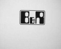
Flip image horizontally
Mirroring around the y-axis. Reverses the pixel order on the x-axis of the sensor (width of the sensor).
Values |
Information |
|
|---|---|---|
BOOL |
0 |
No mirroring (default value). |
1 |
Changes the order of the pixels around the y-axis |
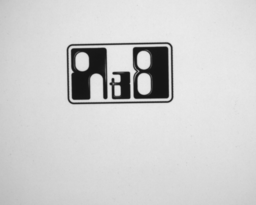
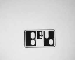
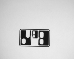
Applying the flip image parameters
Flip image horizontally = 1, flip image vertically = 0
|
|
|---|---|
Flip image horizontally = 0, flip image vertically = 1 |
Flip image horizontally = 1, flip image vertically = 1
|
Information:
The use of the flip image parameters is not recommended for line sensor mode, as this only returns fragmented images as a result.
Flip image vertically
Mirroring around the x-axis. Reverses the pixel order on the y-axis of the sensor (height of the sensor).
Values |
Information |
|
|---|---|---|
BOOL |
0 |
No mirroring (default value). |
1 |
Changes the order of the pixels around the x-axis |
See also Applying the flip image parameters.
Binning
The availability of the parameter depends on the sensor used.
Binning refers to the grouping of neighboring pixels (formation of pixel blocks). Specifically, this parameter creates one (virtual) pixel from 2x2 pixels during image acquisition. The prerequisite for using this parameter is that the image sensor used supports binning.
When binning is enabled, a virtual, higher light sensitivity is calculated for this virtual pixel, which also results in reduced noise. The readout rate at the sensor is also accelerated. The image resolution is reduced, however (due to the combined pixels).
Information:
Binning is part of PixelConfiguration and therefore cannot be active together with parameter Subsampling.
Information:
The maximum height and maximum width of the image are halved when this parameter is active. It is important to note the reduced image sizes when applying the ImageWidth, ImageHeight, ImageOffsetX and ImageOffsetY parameters.
Subsampling
The availability of the parameter depends on the sensor used.
With subsampling, not every pixel is read out (the sampling rate is basically reduced). Specifically, only every second pixel (in the horizontal and vertical directions) is read out with this parameter.
When subsampling is enabled, the readout rate at the sensor is accelerated by reduced image data. The image resolution is reduced, however.
Noise is not affected by subsampling.
Values |
Information |
|
|---|---|---|
BOOL |
0 |
No subsampling (default value). |
1 |
Subsampling (read 1, skip 1) enabled. |
Information:
Subsampling is part of PixelConfiguration and therefore cannot be active together with parameter Binning.
Information:
The maximum height and maximum width of the image are halved when this parameter is active. It is important to note the reduced image sizes when applying the ImageWidth, ImageHeight, ImageOffsetX and ImageOffsetY parameters.
ImageWidth
If the size of the acquired image should be reduced, the maximum width of the image can be reduced with parameter ImageWidth. This allows a faster image acquisition and a shorter image processing time.
For a representation of this parameter in connection with other configuration parameters of the image acquisition, see Image section - Parameters.
Values |
Information |
|
|---|---|---|
UINT |
1 to sensor width |
The default value is the sensor width in pixels. This value is read out from the camera configuration (see WidthMax ). |
Information:
The value is rounded up to values divisible by 32 for 1.3 MP sensors as well as 3.5 MP and 5.3 MP sensors.
ImageWidth automatically rounds up to the next value that can be divided (example: input of 790 is rounded up to 800), but limits it to the permissible image area depending on the sensor. ImageOffsetX is reduced accordingly to ensure that at least the configured image area is acquired. See also Image cropping - Parameter adjustments.
ImageHeight
If the size of the acquired image should be reduced, the maximum height of the image can be reduced with parameter ImageHeight. This allows a faster image acquisition and a shorter image processing time.
For a representation of this parameter in connection with other configuration parameters of the image acquisition, see Image section - Parameters.
Line sensor mode:
After line sensor mode is enabled (see Line sensor), this parameter defines the cutout height.
If less than 16 lines are configured, the bitmap format must be used here instead of the JPEG format otherwise used for displaying the acquired images in the mapp Vision HMI application.
Values |
Information |
|
|---|---|---|
UINT |
1 to sensor height |
The default value is the sensor height in pixels. This value is read out from the camera configuration (see HeightMax ). |
Information:
Value is directly applied for 1.3 MP sensors as well as for 3.5 MP and 5.3 MP sensors.
ImageOffsetX
If the width of the acquired image is reduced, an offset can be defined for the position of the image on the sensor. ImageOffsetX cannot be greater than WidthMax – ImageWidth. The offset is limited to this maximum value.
For a representation of this parameter in connection with other configuration parameters of the image acquisition, see Image section - Parameters.
Values |
Information |
|
|---|---|---|
UINT |
0 to sensor width - 1 |
The default value is 0 (no offset). Unit pixel. |
Information:
The value is rounded down to values divisible by 32 for 1.3 MP sensors as well as 3.5 MP and 5.3 MP sensors.
ImageOffsetY
If the height of the acquired image is reduced, an offset can be defined for the position of the image on the sensor. ImageOffsetY cannot be greater than HeightMax – ImageHeight. The offset is limited to this maximum value.
For a representation of this parameter in connection with other configuration parameters of the image acquisition, see Image section - Parameters.
Values |
Information |
|
|---|---|---|
UINT |
0 to sensor height - 1 |
The default value is 0 (no offset). Unit pixel. |
Information:
Value is directly applied for 1.3 MP sensors as well as for 3.5 MP and 5.3 MP sensors.
Line sensor
The availability of the parameter depends on the sensor used.
Parameter for enabling line sensor mode. The height of a line is defined with parameter ImageHeight. The other associated parameters are active only in line sensor mode.
Values |
Information |
|
|---|---|---|
BOOL |
0 |
The line sensor is disabled (default value). |
1 |
The line sensor is enabled. |
Information:
In line sensor mode, it is possible to use either the internal lighting, which synchronizes the light pulses with image acquisition, or an external continuous light.
LinesPerImage
The availability of the parameter depends on the sensor used.
Number of image acquisitions in static line sensor mode or the maximum line sensor height:
The maximum line sensor height is 4096 for the 1.3 megapixel sensor with a line width of 1280.
The product of configured image height (ImageHeight) and LinesPerImage is therefore not permitted to exceed 4096. Thus, 4096 image acquisitions can be configured for single-line acquisitions (ImageHeight = 1). If ImageHeight is increased (e.g. 1024), LinesPerImage must be reduced accordingly (e.g. 4).
LinesPerImage must also be reduced when using a larger image sensor. The maximum line sensor height is 2048 for the 5.3 megapixel sensor with a line width of 2592.
Information:
The 3.5 megapixel sensor cannot be used as a line sensor!
Values |
Information |
|
|---|---|---|
UINT |
1 to 4096 |
Number of image acquisitions in line sensor mode. The default value is 1. Different maximum values depending on the image sensor used! |
LineScanPeriod
The availability of the parameter depends on the sensor used.
The length of time between image acquisitions configured via LinesPerImage in static line sensor mode.
Values |
Information |
|
|---|---|---|
UDINT |
1 to 4,294,967,295 |
Time between two image acquisitions in line sensor mode from 1 ns to 4.29 s in increments of 1 ns. Although the time between two images can be configured starting with 1 ns, there is a lower limit depending on the image sensor and image acquisition parameters. Maximum line frequency (for an entire line with 1280 pixels): 16 kHz |
When selecting the delay time between two images, the times for an image acquisition and the integration time of the sensor (ExposureTime(n)) must be taken into account.
For the 1.3 megapixel sensor, therefore, the difference (ExposureTime - 31.7 µs) must be added to the permissible LineScanPeriod for times > 31 µs.
The following values for the waiting time result depending on the line height and Binning:
Binning disabled |
Binning enabled |
|
|---|---|---|
1280 x 1 |
68 µs |
63 µs |
1280 x 2 |
74 µs |
67 µs |
1280 x 4 |
85 µs |
76 µs |
1280 x 1024 |
5714 µs |
4466 µs |
For the 5.3 megapixel sensor, the difference (ExposureTime - 29.8 µs) must be added to the permissible LineScanPeriod for times > 29 µs.
The following values for the waiting time result depending on the line height and Binning:
Binning disabled |
Binning enabled |
|
|---|---|---|
2592 x 1 |
319.3 µs |
364.9 µs |
2592 x 2 |
364.9 µs |
364.9 µs |
2592 x 4 |
364.9 µs |
410.5 µs |
2592 x 8 |
410.5 µs |
501.7 µs |
FocusScale
Available on the camera side starting with production date 1951 (year / calendar week).
Settings "mm" and "10 µm" are aligned by the manufacturer. This ensures that the focus of the new camera does not have to be adjusted again when camera hardware is replaced during servicing.
VignettingCorrection
Vignetting refers to the shading towards the edge of the image (light falloff).
An automatic correction can be enabled with this parameter.
Available on the camera side starting with production date 2103 (year / calendar week).
Values |
Information |
|
|---|---|---|
BOOL |
0 |
No correction of vignetting (default value). |
1 |
Vignetting correction enabled. |
LEDTempDriftCorrection
This parameter can be used to enable an automatic correction of the temperature drift of the camera's LED lighting.
Available on the camera side starting with production date 2103 (year / calendar week).
The intensity of the LEDs is adjusted to each other. Slightly less light output is therefore available with LEDTempDriftCorrection enabled. The exposure time will subsequently increase.