本节中指定的参数是硬件模块 I/O 映射的一部分,可通过 Automation Studio 访问。
BOOL |
0 or 1 |
选择数字输出的运行模式 |
W |
|
|
BOOL |
0 or 1 |
启用/禁用图像采集触发器 |
W |
|
|
BOOL |
0 or 1 |
取消 NetTime 触发的图像采集 |
W |
|
|
BOOL |
0 or 1 |
启用/禁用传感器对焦和积分时间搜索 |
W |
|
|
BOOL |
0 or 1 |
启用/禁用红外线滤波器 |
W |
|
|
USINT |
0 to 255 |
设置增益因子 |
W |
|
|
UINT |
0 to 65535 |
将焦点从 "MOD "设置为 "无限 |
W |
|
|
USINT |
0 to 4 |
选择 LED 状态指示条的模式和颜色 |
W |
|
|
UDINT |
1 to 16,777,216 |
以微秒为单位设置传感器的积分时间 |
W |
|
|
DINT |
-2,147,483,648 to 2,147,483,647 |
以微秒为单位设置触发延迟或净时间 |
W |
|
|
USINT |
0 to 255 |
选择机载 LED 灯的 LED 颜色 |
W |
|
|
USINT |
0 to 0x0F |
启用/禁用 LED 段 |
W |
|
|
DINT |
-2,147,483,648 to 2,147,483,647 |
指定动态线路传感器模式的 NetTime。 |
W |
|
|
UDINT |
0 to 4,294,967,295 |
动态线路传感器工作时两次图像采集之间的时间间隔。 |
W |
|
|
BOOL |
0 or 1 |
启用/禁用Chromatic锁定 |
W |
|
DigitalOutput01
启用/禁用摄像机的数字输出。所选值和输出的触发器转发(TriggerForwarding)决定了将采用哪种工作模式。
Operating modes
参数 |
操作方法 |
|
|---|---|---|
DOMode |
DigitalOutput01 |
操作行为 |
0 |
0 |
用户输出不受限制。 |
0 |
1 |
用户输出不受限制。 |
1 |
- |
控制外部照明(TriggerForwarding)。. |
ImageAcquisition
若要进行其他图像采集,必须将该值重置为 0,这样才能进行另一次图像采集。
使用参数 MultiCapture 进行多图像采集时,还必须通过 ImageAcquisition 启用此功能。如果使用 MultiCapture 配置了 NetTime 触发器,则在激活触发器期间不需要 ImageAcquisition 的下降沿和新边沿。只要不重置 ImageAcquisition(下降沿),就可以重置 NetTime。When using multiple
ResetAcquisition
取消带有 NetTime 时间戳(使用TriggerDelay 设置)的未来图像采集。正在进行的图像采集不会被取消。
信息:
启用 SearchAcquisitionSettings 时自动触发。
SearchAcquisitionSettings
该参数也称为静态/触发式自动对焦,可用于寻找图像采集的最佳设置。这是为当前图像区域的焦点和传感器的积分时间(考虑到 LED 的强度)而设置的。
信息:
对于 C 卡口相机,只搜索 ExposureTime(n)。:
值 |
信息 |
|
|---|---|---|
BOOL |
0 |
搜索最佳图像采集值不激活(默认值)。 当下降沿为 0 时,焦点设置为参数 SetFocus 的值,积分时间设置为参数 ExposureTime(n) 的值。 |
1 |
当上升沿为 1 时,将启用搜索最佳积分图像采集值的功能。 只要参数为 1,参数 SetFocus 中的值就会被忽略。 ExposureTime(n)的所有实例中的值也会被忽略。相反,参数 ReadExposureTime 和 ReadFocus 的值将用于所有图像采集。
|
信息:
SearchAcquisitionSettings 是一种辅助机制。有时手动设置 SetFocus 和 ExposureTime(n)
信息:
mapp Vision HMI 应用程序中的 SearchAcquisitionSettings 还提供两个附加参数(请参阅搜索焦点和曝光时间 和 SearchFocusPositionY。
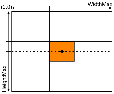
Recommendations for using SearchAcquisitionSettings
•要采集的对象应位于图像区域的中心。
•要采集的物体在任何方向上最多占传感器表面距中心高度或宽度的 1/8。
•焦点处不应出现反射(由于像素过热)。
IRFilter
当使用红外线 LED 光采集图像时,必须使用该参数打开红外线滤光器,这样只有红外线能照射到传感器,避免其他颜色的光干扰。
为防止频繁开关机械滤光片而损坏滤光片,摄像机在每次开关操作后自动提供 500 毫秒的空闲时间。
机械红外滤光片的切换大约需要 100 毫秒,这意味着大约每 600 毫秒可以切换一次。
在实际切换操作过程中(100 毫秒),摄像机状态位 ImageAcquisitionReady 会置 0,但在空闲时间(500 毫秒)内不会置 0。
信息:
相机有一个内部加速度计,当加速度值为 5 m/s2 (大于 0.5 重力加速度)时开始振动,它会自动触发红外滤光片。ImageAcquisitionReady 不受影响!
GainLevel
GainLevel 在从传感器获取图像时应用,可用于放大弱光条件等。
由于增益不仅会放大信号,也会放大噪声,因此应谨慎使用该参数。例如,如果仅靠曝光时间或光照强度无法获得所需的信号!
信息:
参数 GainLevel 允许值的增益系数取决于摄像机变体的传感器类型。
值 |
信息 |
|
|---|---|---|
USINT |
0 |
保留。目前解释为增益因子为 1。 |
1 |
增益因子 1.0(默认值) |
|
2 |
•Python1300: 增益因子 1.9 |
|
3 |
•Python1300: 增益因子 3.5 |
|
4 to 255 |
保留。目前解释为最大增益因子。 |
SetFocus
不适用于 C 卡口相机!
此参数仅适用于带内置镜头的相机型号。
设置对焦。如果参数 SearchAcquisitionSettings 为 1,则此参数的内容将被忽略。
可使用的数值范围取决于所使用的光学器件。此外,非循环参数 FocusScale 允许以 1 mm 或 1/100 mm 增量的原始数据步长或分辨率设置焦距范围。
StatusLED
摄像机开机后,其圆周 LED 状态指示条处于系统模式(POWERLINK 状态)。只有在启动后才能将 LED 切换到用户模式,从而禁用 LED 或将其设置为所选颜色。
值 |
信息 |
|
|---|---|---|
USINT |
0 |
系统模式 = POWERLINK 状态(默认值) |
1 |
用户模式 = LED 禁用 |
|
2 |
用户模式 = LED 绿色 |
|
3 |
用户模式 = LED 红色 |
|
4 |
用户模式 = LED 蓝色 |
|
5 to 255 |
保留 |
信息:
在图像采集期间,LED 状态指示条将被禁用。
ExposureTime(n)
对于带集成照明的型号,该值也相当于 LED 闪光灯的曝光时间。曝光时间限制为 10000 µs。
将曝光时间用作传感器的快门时间时,最大时间仅限于数据点。
信息:
根据参数 MultiCapture 的计算值,该参数(指数为 01、02 等)会出现 n 次。
DelayNetTime(n)
触发延迟时间。如果参数 TriggerDelay = 0,则使用该参数设置的时间作为触发延迟时间。如果参数 TriggerDelay = 1,则使用设定的 NetTime 作为触发时间。
在触发延迟 =0 的情况下,延迟时间总是指接收到数据后的下一个 PLK SoC(周期开始)报文。
如果由于触发事件采集了多幅图像(MultiCapture > 1),则延迟时间始终基于实际触发事件,而不是最后一次采集。
信息:
如果 Nettime 已过,则立即触发。在这种情况下,FailedAcquisitionCnt 和 CompletedAcquisitionCnt 都会增加。
触发延迟 |
值 |
信息 |
|
|---|---|---|---|
DINT |
0 |
0 to 2,147,483,648 |
31 位值,延迟时间为 1 µs 至 2147 s,增量为 1 µs(相对 NetTime)。 不使用 1 个符号位。 |
1 |
-2,147,483,648 to 2,147,483,647 |
用于设置 NetTime 的 32 位值,从 1 µs 到 4294 s,增量为 1 µs(绝对 NetTime)。 |
信息:
根据参数 MultiCapture 的计算值,该参数(指数为 01、02 等)会出现 n 次。
信息:
多个图像采集之间的最小时间差必须大于所用图像传感器配置图像尺寸的最大图像采集时间。在 FPGA 中进行内部图像预处理时,必须加上额外的时间。
FlashColor(n)
此参数用于指定图像采集时使用的 LED 颜色。对于只有一种 LED 颜色的摄像机型号,只需在开始时设置一次该参数。对于具有多种 LED 颜色的摄像机型号,可根据需要在应用过程中进行切换。
如果设置了摄像机没有的 LED 颜色,则在图像采集过程中不会使用灯光!
更多信息,请参阅 ChromaticLock。
值 |
信息 |
|
|---|---|---|
USINT |
0 |
无光(默认值) |
1 |
红光 (625 纳米) |
|
2 |
绿光(525 纳米) |
|
3 |
蓝 (470 纳米) |
|
4 |
青柠 (568 纳米) |
|
99 |
白光 |
|
100 |
红外线 (850 纳米) |
|
210 |
紫外线 (405 纳米) |
|
Rest |
无效 |
信息:
根据参数 MultiCapture 的计算值,该参数(指数为 01、02 等)会出现 n 次。
FlashSegment(n)
该参数指定哪些 LED 段用于图像采集。各种 LED 段可根据需要进行组合切换,并以位模式寻址。
信息:
根据参数 MultiCapture 的计算值,该参数(指数为 01、02 等)会出现 n 次。
参数 CyclicLineScanNettime 仅在 LinesensorMode 设置为 1(循环/动态线路传感器)时有效。
两个线性传感器子图像之间的距离可以通过 CyclicLineScanPeriod 使用此参数循环指定。如果 CyclicLineScanNettime 在过去,则 CyclicLineScanPeriod 始终适用。
CyclicLineScanPeriod
参数 CyclicLineScanPeriod 仅在 LinesensorMode 设置为 1(循环/动态线路传感器)时有效。
ChromaticLock
不适用于 C 卡口相机!
该参数仅适用于带内置镜头的相机型号。
对于每种颜色,焦点都会稍作改变,以提供准确的清晰度。更改 FlashColor 会导致最小程度的自动焦距变化。在这种情况下,摄像机处于忙碌状态,不会接受触发。
默认情况下,更改 FlashColor 时会重新调整到相应的焦距值。如果启用了 ChromaticLock,则在更改焦距值时不会进行重新调整。
信息:
建议将 ChromaticLock 用于高速换色的应用。
对于不需要快速更换 LED 颜色的应用,建议先更换颜色,等到相机再次准备就绪时再触发新图像。
The parameters specified in this section are part of the I/O mapping of the hardware module that can be accessed via Automation Studio.
BOOL |
0 or 1 |
Selects the mode of operation of the digital output |
W |
|
|
|---|---|---|---|---|---|
BOOL |
0 or 1 |
Enables/Disables the trigger for the image acquisition |
W |
|
|
BOOL |
0 or 1 |
Cancels an image acquisition triggered by NetTime |
W |
|
|
BOOL |
0 or 1 |
Enables/Disables search for focus and integration time of the sensor |
W |
|
|
BOOL |
0 or 1 |
Enables/Disables the infrared filter |
W |
|
|
USINT |
0 to 255 |
Sets a gain factor |
W |
|
|
UINT |
0 to 65535 |
Sets the focus from "MOD" to "Infinity" |
W |
|
|
USINT |
0 to 4 |
Selects the mode and color of the LED status indicator bars |
W |
|
|
UDINT |
1 to 16,777,216 |
Sets the integration time of the sensor in microseconds |
W |
|
|
DINT |
-2,147,483,648 to 2,147,483,647 |
Sets Delay or NetTime for the trigger in microseconds |
W |
|
|
USINT |
0 to 255 |
Selects LED colors of the onboard LED lighting |
W |
|
|
USINT |
0 to 0x0F |
Enables/Disables LED segments |
W |
|
|
DINT |
-2,147,483,648 to 2,147,483,647 |
Specifies the NetTime for dynamic line sensor mode. |
W |
|
|
UDINT |
0 to 4,294,967,295 |
Time between 2 image acquisitions in dynamic line sensor operation. |
W |
|
|
BOOL |
0 or 1 |
Enables/Disables ChromaticLock |
W |
|
DigitalOutput01
Enable/disable digital output of the camera. The value selected and TriggerForwarding of the output determine which operating mode will be applied.
Values |
Information |
|
|---|---|---|
BOOL |
0 |
DigitalOutput01 is passive (default value). |
1 |
DigitalOutput01 is active (source). |
Operating modes
Method of operation |
||
|---|---|---|
DOMode |
DigitalOutput01 |
Operating behavior |
0 |
0 |
Unrestricted use for user output. |
0 |
1 |
Unrestricted use for user output. |
1 |
- |
Control of external lighting (TriggerForwarding). |
ImageAcquisition
Trigger to enable the image acquisition. A positive edge of this parameter enables the image acquisition.
In order to enable additional image acquisitions, this value must be reset to 0 so that another image acquisition is possible.
Values |
Information |
|
|---|---|---|
BOOL |
0 |
Do not acquire an image (default value). |
1 |
Image acquisition enabled. |
When using multiple image acquisition using parameter MultiCapture, this must also be enabled via ImageAcquisition. If a NetTime trigger is configured with MultiCapture, a falling and new edge of ImageAcquisition during an active trigger is not necessary. As long as ImageAcquisition is not reset (falling edge), it is possible to reset the NetTime.
ResetAcquisition
Cancels a future image acquisition with NetTime timestamp (set using TriggerDelay). An image acquisition in progress is not canceled.
Information:
Automatically triggered when SearchAcquisitionSettings enabled.
SearchAcquisitionSettings
Also known as static/triggered autofocus, this parameter can be used to find optimal settings for the image acquisition. This is done for the current image field for the focus and integration time of the sensor (taking the LED intensity into account).
Information:
Only ExposureTime(n) is searched for with C mount cameras.
Values |
Information |
|
|---|---|---|
BOOL |
0 |
Searching for optimal image acquisition values is not active (default value). With a falling edge to 0, the focus is set on the value of parameter SetFocus and the integration time is set to the value of parameter ExposureTime(n). |
1 |
On a rising edge to 1, the search for the optimal integration image acquisition values is enabled. As long as the parameter is 1, the value in parameter SetFocus is ignored. The values in all instances of ExposureTime(n) are also ignored. Instead, the values of parameters ReadExposureTime and ReadFocus are used for all image acquisitions. |
Information:
SearchAcquisitionSettings is a supporting mechanism. Better results can sometimes be achieved by setting SetFocus and ExposureTime(n) manually.
Information:
Two additional parameters are available for SearchAcquisitionSettings in the mapp Vision HMI application (see Searching for the focus and exposure time). SearchFocusPositionX and SearchFocusPositionY.
Recommendations for using SearchAcquisitionSettings
•The object to be acquired should be located in the center of the image area.
•The object to be acquired should occupy a maximum of 1/8 of the height or width of the sensor surface from the center in any direction.
•No reflections should occur at the focal point (due to hot pixels).
IRFilter
Parameter for enabling a mechanical infraredfilter in front of the image sensor.
When using infrared LED light for image acquisition, the infrared filter must be switched on with the parameter so that only IR light hits the sensor and disturbing influences of the other light colors are avoided.
Values |
Information |
|
|---|---|---|
BOOL |
0 |
Disables the infrared filter. Wavelength range 420 nm to 680 nm. |
1 |
Enables the infrared filter. Wavelength range 735 nm to 1050 nm |
To prevent damaging the mechanical filter by frequently switching it on and off, the camera offers an automatic idle time of 500 ms after each switching operation.
Switching the mechanical infrared filter takes approx. 100 ms, which means that switching can take place approximately every 600 ms.
During the actual switching operation (100 ms), camera status bit ImageAcquisitionReady falls to 0, but not during the idle time (500 ms).
Information:
The camera has an internal accelerometer that automatically triggers the infrared filter in the event of vibration starting at an acceleration value of 5 m/s2 (> 0.5 gravitational acceleration). ImageAcquisitionReady is not affected!
GainLevel
This parameter selects a gain factor for the grayscale values of an image.
GainLevel is applied during image acquisition from the sensor and can be used to amplify low-light conditions, for example.
Since the gain amplifies not only the signal but also the noise, this parameter should be used with caution. For example, if it is not possible to achieve the required signal through exposure time or light intensity alone!
Information:
The gain factors for permitted values of parameter GainLevel depend on the sensor type of the camera variant.
Values |
Information |
|
|---|---|---|
USINT |
0 |
Reserved. Currently interpreted as a gain factor of 1. |
1 |
Gain factor 1.0 (default value) |
|
2 |
•Python1300: Gain factor 1.9 |
|
3 |
•Python1300: Gain factor 3.5 |
|
4 to 255 |
Reserved. Currently interpreted as the maximum gain factor. |
SetFocus
Not for C mount cameras!
This parameter is only available for camera variants with a built-in lens.
Sets the focus setting. The contents of this parameter are ignored if parameter SearchAcquisitionSettings is 1.
The usable range of values depends on the optics used. In addition, acyclic parameter FocusScale permits the scaling of the focus range of values to be set in raw data steps or resolutions of 1 mm or 1/100 mm increments.
Values |
Information |
|
|---|---|---|
UINT |
0 to 65535 |
Sets the focus setting from the near range (Minimum Object Distance) to the far range (infinity). |
StatusLED
After the camera is switched on, its circumferential LED status indicator bar is in system mode (POWERLINK state). Only after startup can the LEDs be switched to user mode, allowing them to either be disabled or set to a selected color.
Values |
Information |
|
|---|---|---|
USINT |
0 |
System mode = POWERLINK status (default value) |
1 |
User mode = LED disabled |
|
2 |
User mode = LED green |
|
3 |
User mode = LED red |
|
4 |
User mode = LED blue |
|
5 to 255 |
Reserved |
Information:
The LED status indicator bar is disabled for the duration of the image acquisition.
ExposureTime(n)
Integration time of the sensor.
For variants with integrated lighting, this value also corresponds to the exposure time of the LED flash. The ExposureTime is limited to 10000 µs.
When using the ExposureTime as ShutterTime of the sensor, the maximum time is limited to the data point.
Values |
Information |
|
|---|---|---|
UDINT |
1 to 16,777,216 |
24-bit value for an integration time of 1 µs to 16.8 s in increments of 1 µs. |
Information:
Depending on the calculated value of parameter MultiCapture, this parameter (with indices 01, 02, etc.) occurs n times.
DelayNetTime(n)
Delay time for the trigger. If parameter TriggerDelay = 0, the time set in this parameter is used as the delay time for the trigger. If parameter TriggerDelay = 1, the set NetTime is used as the time for the trigger.
In case of TriggerDelay =0, the delay time always refers to the next PLK SoC (Start of Cycle) telegram after receiving the data.
If multiple images are acquired due to a trigger event (MultiCapture > 1), the delay is always based on the actual trigger event and not the last acquisition.
Information:
Triggering takes place immediately if Nettime is in the past. In this case, both FailedAcquisitionCnt and CompletedAcquisitionCnt are increased.
TriggerDelay |
Values |
Information |
|
|---|---|---|---|
DINT |
0 |
0 to 2,147,483,648 |
31-bit value for a delay time of 1 µs to 2147 s in increments of 1 µs (relative NetTime). 1 sign bit is not used. |
1 |
-2,147,483,648 to 2,147,483,647 |
32-bit value for set NetTime from 1 µs to 4294 s in increments of 1 µs (absolute NetTime). |
Information:
Depending on the calculated value of parameter MultiCapture, this parameter (with indices 01, 02, etc.) occurs n times.
Information:
The minimum time difference between multiple image acquisitions must be greater than the maximum image acquisition time for the configured image size of the image sensor used. During internal image pre-processing in FPGA, additional times must be added to this.
FlashColor(n)
This parameter specifies which LED color should be used during image acquisition. For a camera variant with a single LED color, this parameter must only be set once at the beginning. For camera variants with multiple LED colors, these can consequently be switched during application depending on the requirements.
If an LED color is set that the camera does not have, no light is used during image acquisition!
For further information, see also ChromaticLock.
Values |
Information |
|
|---|---|---|
USINT |
0 |
No light (default value) |
1 |
Red (625 nm) |
|
2 |
Green (525 nm) |
|
3 |
Blue (470 nm) |
|
4 |
Lime (568 nm) |
|
99 |
White |
|
100 |
Infrared (850 nm) |
|
210 |
Ultraviolet (405 nm) |
|
Rest |
Invalid |
Information:
Depending on the calculated value of parameter MultiCapture, this parameter (with indices 01, 02, etc.) occurs n times.
FlashSegment(n)
This parameter specifies which LED segments should be used for the image acquisition. The various LED segments can be switched in combinations as required and are addressed as bit patterns.
Values |
Information |
|
|---|---|---|
USINT |
Bit 0 |
LED segment 1 on/off |
Bit 1 |
LED segment 2 on/off |
|
Bit 2 |
LED segment 3 on/off |
|
Bit 3 |
LED segment 4 on/off |
Information:
Depending on the calculated value of parameter MultiCapture, this parameter (with indices 01, 02, etc.) occurs n times.
Parameter CyclicLineScanNettime is only active if LinesensorMode is set to 1 (cyclic/dynamic line sensor).
Values |
Information |
|
|---|---|---|
DINT |
-2,147,483,648 to 2,147,483,647 |
Specifies the NetTime for dynamic line sensor mode. |
The distance between two line sensor subimages can be specified cyclically with this parameter using CyclicLineScanPeriod. CyclicLineScanPeriod is always applied if CyclicLineScanNettime is in the past.
CyclicLineScanPeriod
Parameter CyclicLineScanPeriod is only active if LinesensorMode is set to 1 (cyclic/dynamic line sensor).
Values |
Information |
|
|---|---|---|
UDINT |
0 to 4,294,967,295 |
Time between 2 image acquisitions in line sensor mode from 0 to 4.29 s in increments of 1 ns. |
ChromaticLock
Not for C mount cameras!
This parameter is only available for camera variants with a built-in lens.
For each color the focus changes a little bit to provide the exact sharpness. Changing the FlashColor leads to a minimal automatic focus change. In this case the camera is busy and will not accept a trigger.
By default, readjustment to the corresponding focus value takes place when FlashColor is changed. If ChromaticLock is enabled, readjustment does not take place when changing the focus value.
Values |
Information |
|
|---|---|---|
BOOL |
0 |
ChromaticLock disabled (default value). |
1 |
Enables ChromaticLock. |
Information:
ChromaticLock is recommended for applications with high-speed color changing.
For applications that do not require a fast change between LED colors, it is recommended to change the color first and wait until the camera is ready again to trigger the new image.