本节介绍图像采集和配置 B&R 视觉相机的所有相关标准参数。标准配置包括狭义图像采集(包括集成照明和线性滤波器预处理)、可选的线性传感器操作和数字输出配置。
图像采集
图像采集及其属性代表了相机的基本功能,因为良好的图像采集总是能简化后续图像处理或视觉功能的应用。
在机器视觉中,图像采集是通过 Automation Studio 在视觉应用程序中进行配置的。参数位于摄像机的 I/O 映射中。
图像采集设置包括各种触发参数(触发源、触发类型、定时等)、周期和曝光时间设置、板载 LED 照明以及各种采集图像计数器和状态位。
图像采集还定义了聚焦、低照度放大、图像在 x/y 方向上的镜像、特殊 CMOS 传感器侧图像读出配置(分档、子采样等)以及图像切口及其在采集图像中的位置。
图像采集和后续图像处理 - 时序图
该时序图是显示选定图像采集参数随时间变化过程的示意图。所示长度与实际持续时间不符。还需注意的是,时间取决于所选的图像处理任务和图像内容。
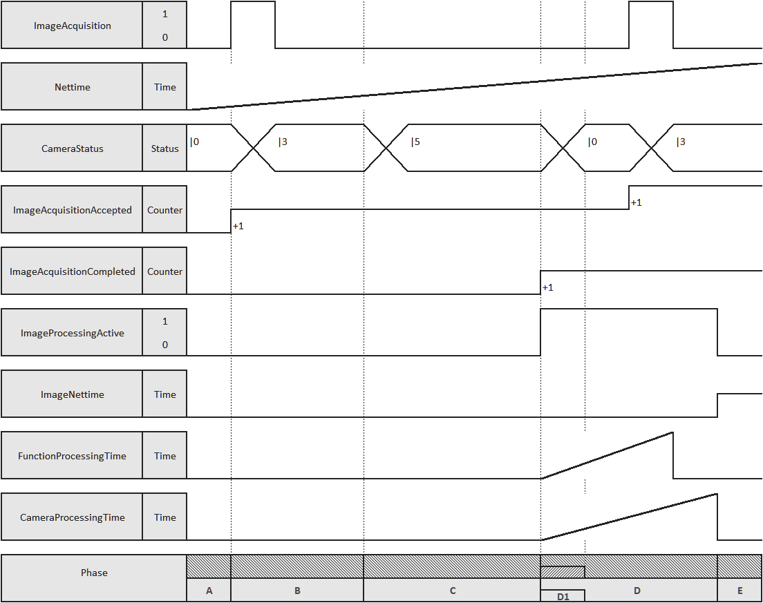
摄像机准备就绪。等待触发。 用计数器记录接受的图像采集。 |
B |
达到设定的 NetTime 触发器之前的时间。 |
|
|---|---|---|---|
C |
读取曝光时间和传感器 |
D |
用计数器记录所接受的图像采集。图像处理启动。记录视觉功能和相机(操作系统)的处理时间。更改 ImageNettime。 |
D1 |
可以获取新图像(CameraStatus = 0)。 |
E |
用于获取第一幅图像的相机的图像处理和处理时间结束。 |
信息:
一旦第一张获取的图像的图像处理和摄像机处理时间结束(上图中的 E 阶段),该图像即可用。每多获取一幅图像,ImageNettime 就会改变。
如果连续获取多幅图像,ImageProcessingActive 将一直处于准备状态,直到处理完所有获取的图像。要获得相应图像的正确结果,必须在应用程序中检查 ImageNettime 是否发生变化。
信息:
CameraProcessingTime 的抖动很低。这对于智能传感器变体来说可以忽略不计,但对于智能摄像头变体来说,每个视觉功能都会增加抖动!
信息:
POWERLINK 网络图像处理的输入数据在实际(Nettime)触发时应用。
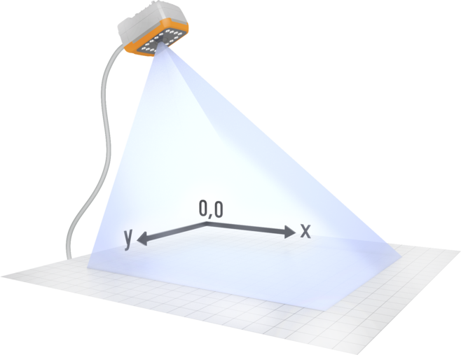
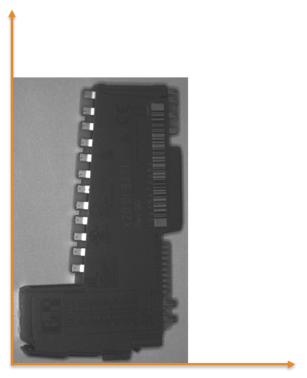
目标物体的坐标系
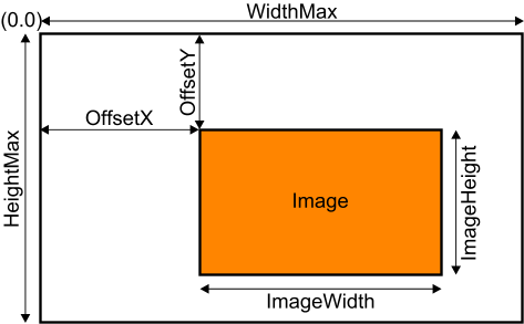
图像部分 - 参数
下图显示了以下图像采集配置参数之间的关系:
•图像的最大宽度 - ImageWidth
•图像的最大高度 - ImageHeight
•图像在 x 轴上的偏移 - ImageOffsetX
•图像在 y 轴上的偏移量 - ImageOffsetY
•所用传感器的最大图像宽度- WidthMax
•所用传感器的最大图像高度 - HeightMax
信息:
图像采集数据(循环读取)、图像采集参数(循环写入)、图像采集配置(非循环读取)和图像采集配置(非循环写入)中描述了用于配置图像采集的寄存器。
信息:
在图像采集配置(非循环写入)寄存器中可以找到线路传感器操作(LinesensorMode)的各个参数。
预处理(线性滤波器)
通过选择现有的或用户自定义的滤镜,可以对相机进行预处理。在此过程中,缩放图像的灰度值会经过计算校正。预处理的目的可以是
•减少噪音和个别图像干扰
•平滑(模糊)图像
•边缘检测(单向或多向)
图像预处理使用线性滤波器,这种滤波器由一个 3x3 矩阵组成,在这种情况下,矩阵的系数是可定义的。使用这些矩阵时,预处理并不总是只应用于单个像素;相反,每个像素的 "邻域 "也会被考虑在内(要过滤的特定像素会被检测到矩阵的中心)。
|
|
|
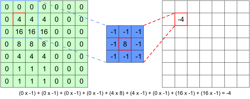
滤波是通过卷积的数学方法完成的。3x3 矩阵,即 "滤波器核心",在图像上逐个像素移动,所有被覆盖的像素都乘以滤波器核心的相应系数。然后将所有九个乘积相加,最后用结果覆盖原始像素的值。这意味着原始像素被替换为其本身及其紧邻像素的加权和。
上述卷积法对于边缘像素并不适用,因为这些像素的一侧或两侧没有相邻像素,无法与相关滤波系数的值相乘。因此,边缘线和边缘列被加倍并添加到实际图像的外部。
通过随后的偏移和增益校正,将结果移位或缩放回采集图像的数值范围内。
这就是滤波图像的结果: 滤波矩阵 x 原始图像 x 增益 + 偏移。
有关用于配置线性滤波器的寄存器,请参阅预处理配置(非循环写入)。
信息:
有关涉及摄像机标准配置的用例,请参阅使用 NetTime 触发图像采集。
有关摄像机标准配置的常见问题,请参阅图像采集常见问题。
本节主题
This section describes the image acquisition and all related standard parameters for configuring a B&R vision camera. The standard configuration includes image acquisition in the narrower sense (including integrated lighting and preprocessing with linear filters), optional line sensor operation and configuration of the digital output.
Image acquisition
Image acquisition and its properties represent the basic function of a camera since good image acquisition always simplifies subsequent image processing or application of a vision function.
With machine vision, image acquisition is configured in the vision application via Automation Studio. The parameters are located in the I/O mapping of the camera.
The image acquisition settings include various trigger parameters (trigger source, trigger type, timing, etc.), settings for cycle and exposure times and for onboard LED illumination as well as the various acquired image counters and status bits.
Image acquisition also defines the focus, low-light amplifications, mirroring of the image in the x/y-direction, special CMOS sensor-side image readout configurations (binning, subsampling, etc.), as well as image cutouts and their position in the acquired image.
Image acquisition and subsequent image processing - Timing diagram
This timing diagram is a schematic diagram showing the course of selected image acquisition parameters over time. The lengths shown are not to scale with respect to the actual durations. It is also important to note that the times depend on the selected image processing task and image content.
Camera ready for operation. Waiting for trigger. An accepted image acquisition is recorded with a counter. |
B |
Time until the set NetTime trigger is reached. |
|
|---|---|---|---|
C |
Reading exposure time and sensor |
D |
The accepted image acquisition is recorded with a counter. The image processing is active. The processing time of the vision function and camera (operating system) is recorded. Changing ImageNettime. |
D1 |
New image acquisition possible (CameraStatus = 0). |
E |
Image processing and processing time of the camera used to acquire the first image is completed. |
Information:
As soon as the image processing and processing time of the camera of the first acquired image is finished (phase E in the previous diagram), this image is available. ImageNettime changes with each additional acquired image.
If several images are acquired in succession, ImageProcessingActive is constantly ready until all acquired images are processed. To get the correct results for the corresponding image, ImageNettime must be checked in the application as to whether it has changed or not.
Information:
CameraProcessingTime has low jitter. This is negligible for Smart Sensor variants, but for Smart Camera variants it adds up with every vision function!
Information:
The input data for image processing by the POWERLINK network is applied at the time of the actual (Nettime) trigger.
Coordinate system at the target object
Image section - Parameters
The figure shows the relationship of the following image acquisition configuration parameters:
•Max. width of the image - ImageWidth
•Max. height of the image - ImageHeight
•Offset for the image on the x-axis - ImageOffsetX
•Offset for the image on the y-axis - ImageOffsetY
•Max. image width of the sensor used - WidthMax
•Max. image height of the sensor used - HeightMax
The registers used to configure image acquisition are described in Image acquisition data (cyclic read), Image acquisition parameters (cyclic write), Image acquisition configuration (acyclic read) and Image acquisition configuration (acyclic write).
The individual parameters for the line sensor operation (LinesensorMode) can be found in the Image acquisition configuration (acyclic write) register.
Preprocessing (linear filters)
Preprocessing can already be carried out on the camera by selecting existing or user-defined filters. In this process, the grayscale values of the indented image are subjected to a computational correction. Objectives of preprocessing can be:
•Reduction of noise and individual image disturbances
•Smoothing (blurring) the image
•Edge detection (single or multi-directional)
Image preprocessing uses linear filters, which consist of a 3x3 matrix with definable coefficients in this case. Using these matrices, preprocessing is not always applied only to individual pixels; instead, the "neighborhood" of each pixel is also taken into account (the specific pixel to be filtered is detected with the center of the matrix).
|
|
|
The filtering is done mathematically via a convolution. The 3x3 matrix, the "filter core", is moved pixel by pixel over the image, and all covered pixels are multiplied by the respective coefficients of the filter core. All nine products are then added, and finally, the value of the original pixel is overwritten with the result. This means that the original pixel is replaced with a weighted sum of itself and its immediate neighboring pixels.
The convolution described above does not work readily for the pixels located on the edge since these have no neighboring pixels on one or two sides with whose values the associated filter coefficients can be multiplied. The margin lines and margin columns are therefore doubled and added to the outside of the actual image.
The results are shifted or scaled back into the range of values of the acquired image via subsequent offset and gain correction.
This is the result for the filtered image: Filter matrix x Original image x Gain + Offset.
For the registers used to configure the linear filters, see the Preprocessing configuration (acyclic write).
For use cases involving the standard configuration of the camera, see Triggering image acquisition with NetTime.
For FAQ about the standard configuration of the camera, see Image acquisition FAQ.
Topics in this section:
•Image acquisition data (cyclic read)
•Image acquisition parameters (cyclic write)
•Image acquisition configuration (acyclic read)
•Image acquisition configuration (acyclic write)